Electromagnetic switch

An electromagnetic switch, electromagnetic coil technology, applied in electromagnetic relays, electromagnetic relay details, circuits, etc., can solve the problems that the conductive clip cannot be in good contact, the electromagnetic coil is not reliable, and achieves easy processing and reduces installation time. , the effect of limiting effect is good

Pending Publication Date: 2018-08-28
浙江中凯科技股份有限公司
View PDF11 Cites 0 Cited by
  • Summary
  • Abstract
  • Description
  • Claims
  • Application Information

AI Technical Summary

Problems solved by technology

[0003] The electromagnetic switch is powered by the electromagnetic coil to provide the pull-in power. Generally, a conductive clip is connected in series in the electromagnetic coil circuit. The conductive clip can control the on-off state of the contact in the conductive clip through the mechanical cooperation method of the operating mechanism, and the contact is fixed. On the conductive clip, the contact plate in contact with the contact is electrically connected to the electromagnetic coil. The contact controls the energization and power loss of the electromagnetic coil by contacting and separating from the contact plate. The conductive clip is generally fixed on the bracket. In the prior art The electromagnetic switch of the electromagnetic switch usually fixes the end of the conductive sheet away from the contact on the bracket, and the end with the contact is the movable end and is in contact with or separated from the contact plate under the action of the operating mechanism. When inaccurate, the conductive clip may not be able to make quick and good contact with the contact plate, making the electromagnetic coil unreliable on and off

Method used


Image

  • Electromagnetic switch
  • Electromagnetic switch
  • Electromagnetic switch

Examples


Embodiment Construction

[0050] The technical solutions of the present invention will be clearly and completely described below in conjunction with the accompanying drawings. Obviously, the described embodiments are part of the embodiments of the present invention, rather than all of them. Based on the embodiments of the present invention, all other embodiments obtained by those of ordinary skill in the art without creative work shall fall within the protection scope of the present invention.

[0051] In addition, the technical features involved in the different embodiments of the present invention described below can be combined with each other as long as there is no conflict between them.

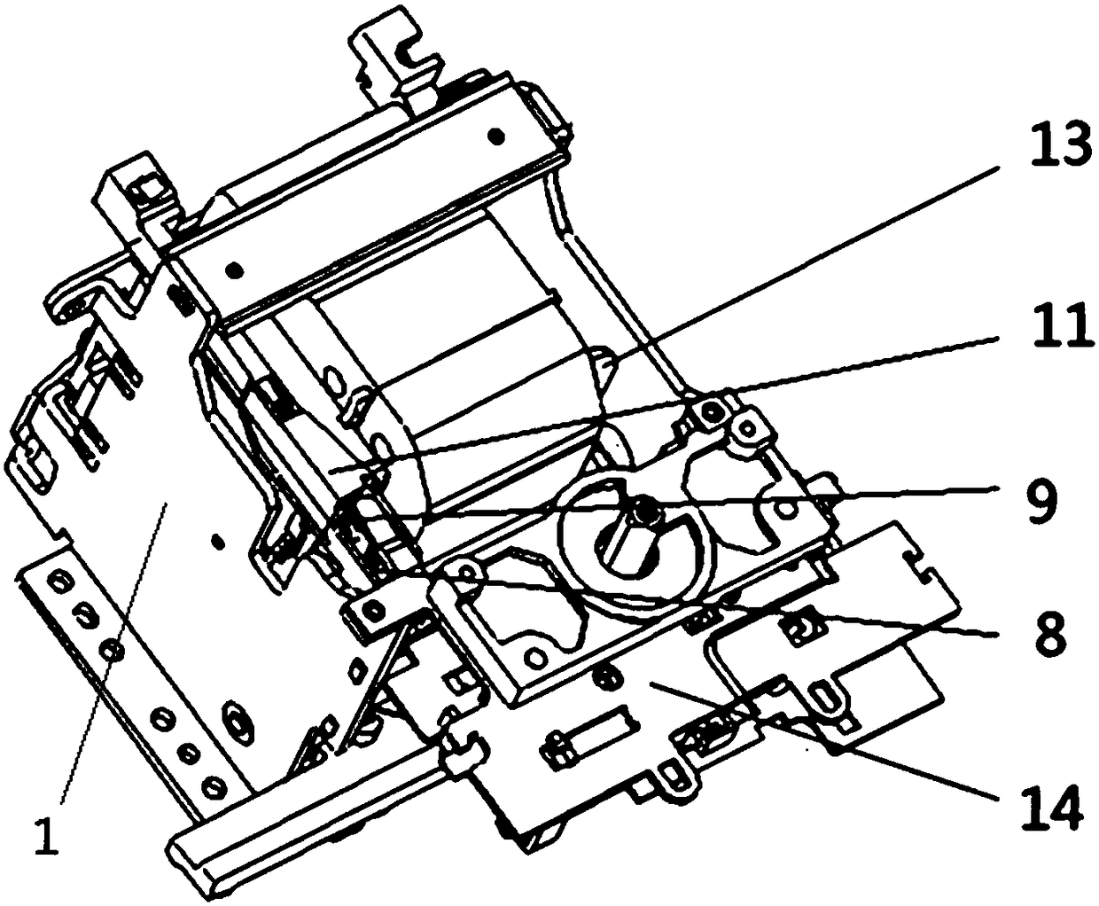
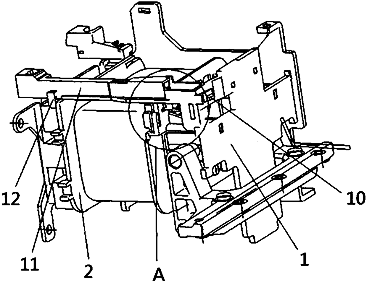
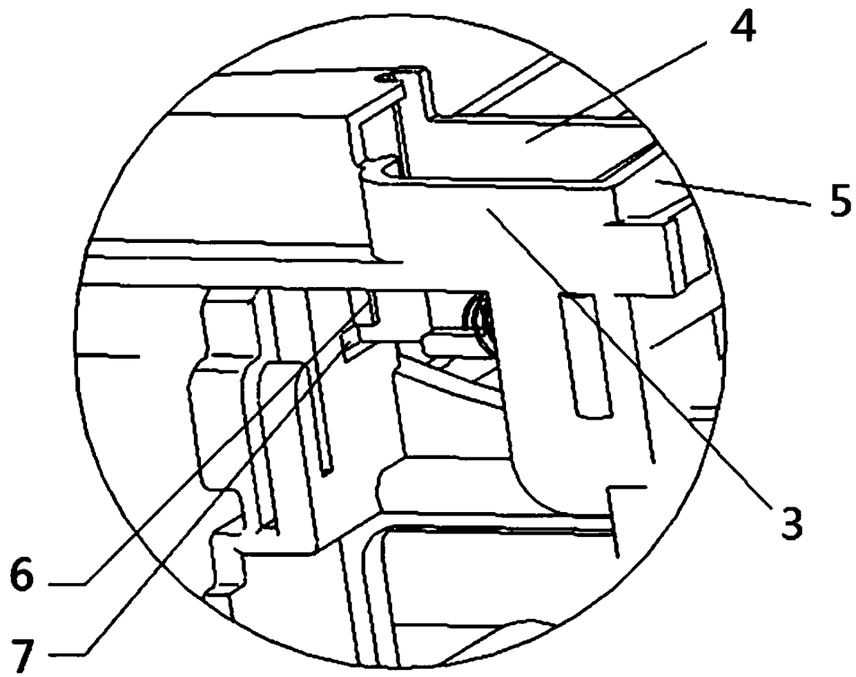
[0052] Such as Figure 1-Figure 8 What is shown is a specific implementation of the electromagnetic switch involved in the present invention. The electromagnetic switch includes a frame, an electromagnetic coil 13, a conductive structure, and a first limit structure.

[0053] In this embodiment, the frame body includes...


PUM


Abstract

The invention relates to the technical field of switches, in particular to an electromagnetic switch. The electromagnetic switch comprises a frame body, an electromagnetic coil, an electric conductingstructure and a first limiting structure, wherein the electromagnetic coil is mounted on the frame body; the electric conducting structure is connected to the coil first end of the electromagnetic coil, the electric conducting structure comprises an electric conducting body and a running end arranged at one end of the electric conducting body, the running end can be in contact with the coil second end of the electromagnetic coil so as to make the electromagnetic coil to be powered on, and the running end can be separated from the coil second end to enable the electromagnetic coil to be powered off; and the first limiting structure is fixedly arranged on the frame body, and can limit the separation amplitude of the running end relative to the coil second end. The electromagnetic switch canenable the electromagnetic coil to be powered on and off more reliably by arranging the limiting structure.

Description

Technical field [0001] The invention relates to the technical field of switches, in particular to an electromagnetic switch. Background technique [0002] The electromagnetic switch, as the name implies, is a switch controlled by an electromagnet, which is a combination of an electromagnet and a switch. When the electromagnet coil is energized, electromagnetic attraction is generated, and the movable iron core pushes or pulls the switch contacts to close, thereby connecting the control circuit. Electromagnetic switches are widely used in various industries. [0003] The electromagnetic switch is powered by the electromagnetic coil to provide the pull-in power. Generally, a conductive clip is connected in series in the electromagnetic coil loop. The conductive clip can control the on-off state of the contact in the conductive clip through the operating mechanism by mechanical cooperation, and the contact is fixed. On the conductive clip, the contact plate in contact with the conta...

Claims


Application Information

Patent Timeline
Patent Type & Authority Applications(China)
IPC IPC(8): H01H50/44
CPCH01H50/44H01H50/443H01H2050/446
Inventor 朱奇敏苏文智穆茂林田新疆屠瑜权屠旭慰
Owner 浙江中凯科技股份有限公司
Why Eureka
Try Eureka