Hydraulic sludge discharging system
A mud system and hydraulic technology, which is applied in the field of sludge removal and discharge at the bottom of sedimentation tanks or thickeners, can solve the problems of high energy consumption, achieve short sludge discharge cycle, high sludge discharge efficiency, and low energy consumption Effect
- Summary
- Abstract
- Description
- Claims
- Application Information
AI Technical Summary
Problems solved by technology
Method used
Image
Examples
Embodiment 1
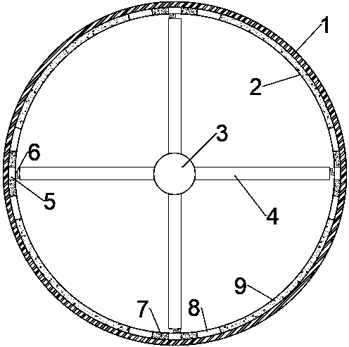
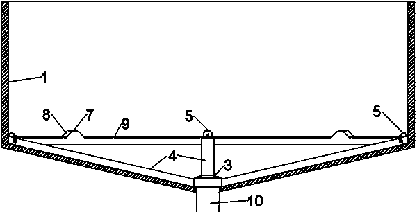
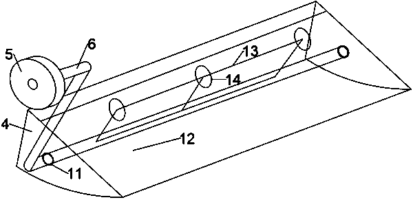
[0025] Embodiment 1: as Figure 1-6 As shown, a hydraulic mud discharge system is arranged at the bottom of the sedimentation tank 1, including a rotating mud collecting cap 3, a mud suction arm 4, a pulley 5, a pulley rod 6, a pulley platform 2 and a mud discharge pipe 10, wherein The mud discharge pipe 10 is fixedly arranged at the center of the bottom of the sedimentation tank 1, and communicates with the outside of the pond. The rotating mud collecting cap 3 is arranged on the upper end of the mud discharging pipe 10, and the inner end of the mud suction arm 4 is fixedly arranged on the rotating mud collecting cap. 3, the inner cavity of the suction arm 4 is in fluid communication with the inner cavity of the rotary suction cap 3, and the pulley 5 is rotatably connected to the outer end of the suction arm 4 through a pulley rod 6, and the suction arm 4 Suction mud gate 12 is provided on it.
[0026] The rotating mud collecting cap 3 is rotationally sealed with the upper e...
Embodiment 2
[0038] Embodiment 2: different from embodiment 1, such as Figure 7-9 As shown, the upper end of the dredging gate 12 is hinged on the upper part of the dredging arm 4 through a hinge 16, and its lower end is movably overlapped on the upper edge of the dredging plate 17, and the two sides of the dredging gate 12 are respectively vertical The side plate 21 of the suction gate is fixedly provided, wherein, the side plate 21 of the suction gate located on one side of the rotary mud collecting cap 3 is provided with an opening 22 of the side plate of the suction gate to serve as the sewage in the inner cavity of the suction arm 4. The opening for the muddy water to flow into the rotating mud collecting cap 3, the size and location of the side plate opening 22 of the dredging gate are just so that when the dredging gate 12 is at the maximum opening, its side is closed.
[0039] The low platform 9 has a certain length, so that the pulley 5 can slide along the low platform 9 for a ce...
PUM
 Abstract
Description
Claims
Application Information
 - R&D
- Intellectual Property
- Life Sciences
- Materials
- Tech Scout
- Unparalleled Data Quality
- Higher Quality Content
- 60% Fewer Hallucinations
Browse by: Latest US Patents, China's latest patents, Technical Efficacy Thesaurus, Application Domain, Technology Topic, Popular Technical Reports.
© 2025 PatSnap. All rights reserved.Legal|Privacy policy|Modern Slavery Act Transparency Statement|Sitemap|About US| Contact US: help@patsnap.com


