
Threading mechanism

A thread and frame technology, applied in the field of zipper manufacturing, can solve problems such as tool damage, achieve good results, high efficiency, and ingenious design

Inactive Publication Date: 2018-08-31
嘉善强锐五金制品厂(普通合伙)
View PDF7 Cites 0 Cited by
  • Summary
  • Abstract
  • Description
  • Claims
  • Application Information

AI Technical Summary

Problems solved by technology

[0002] In the process of processing fasteners with external threads, it is necessary to perform external tapping or cutting to process the external threads. During the process of processing, the tool will lack the necessary buffer due to the impact force. In case of tool damage

Method used


Image

  • Threading mechanism
  • Threading mechanism
  • Threading mechanism

Examples


Embodiment Construction

[0017] In order to make the technical means, creative features, goals and effects of the invention easy to understand, the invention will be further elaborated below in combination with illustrations and specific embodiments.

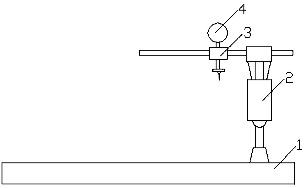
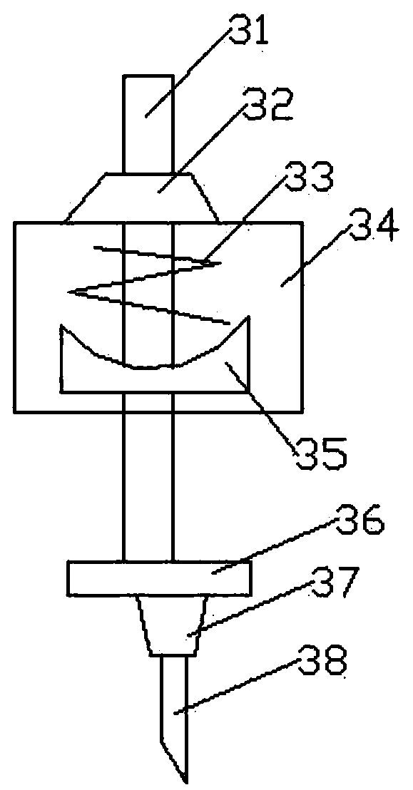
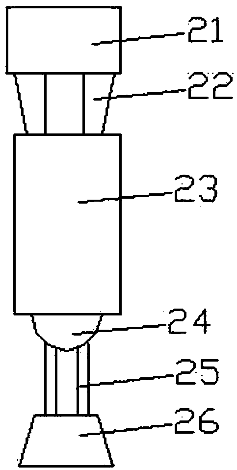
[0018] combine Figure 1 to Figure 3 The inventive threading mechanism will be described in detail.

[0019] A threading mechanism, comprising a base 1, and also comprising a first frame 2 clamped on one end of the upper side of the base 1, a processing part 3 clamped on the first frame 2 and screwed on the The first motor 4 at the upper end of the processing part 3;

[0020] The processing part 3 includes a cube-shaped transmission box 34, a round rod-shaped output shaft 31 pierced in the transmission box 34, screwed on the output shaft 31 by threads and pressed against the transmission box The truncated first guide seat 32 at the upper end of 34 is screwed onto the output shaft 31 and the bearing member 35 pressed against the bottom of the transmiss...


PUM


Abstract

The invention relates to the technical field of zipper manufacturing, and particularly relates to a threading mechanism. The threading mechanism comprises a base, a first rack, a processing componentand a first motor, wherein the first rack is clamped on one end of the upper side of the base, the processing component is clamped on the first rack, and the first motor is screwed to the upper end ofthe processing component. The threading mechanism has the advantages of high threading efficiency and good effect, the processing component is buffered by virtue of a spring, and the processing component is skillfully designed.

Description

technical field [0001] The invention relates to the technical field of zipper manufacturing, in particular to a thread engraving mechanism. Background technique [0002] In the process of processing fasteners with external threads, it is necessary to perform external tapping or cutting to process the external threads. During the process of processing, the tool will lack the necessary buffer due to the impact force. Tool damage has occurred. Contents of the invention [0003] The purpose of the invention is to provide a screw threading mechanism. [0004] The technical solutions adopted by the invention to solve its technical problems are: [0005] A threading mechanism, comprising a base, a first frame clamped on one end of the upper side of the base, a processing part clamped on the first frame, and a processing part screwed to the processing part The first motor at the upper end; [0006] The processing part includes a cube-shaped transmission box, a round rod-shaped...

Claims


Application Information

Patent Timeline
Patent Type & Authority Applications(China)
IPC IPC(8): B23G1/00B23G1/44
CPCB23G1/00B23G1/44B23G2210/08
Inventor 车崇庆
Owner 嘉善强锐五金制品厂(普通合伙)
Learn More