Auxiliary supporting clamp for thin-walled part edge and hole machining and working method of auxiliary supporting lamp

A thin-walled parts and auxiliary support technology, applied in manufacturing tools, metal processing equipment, metal processing machinery parts, etc., can solve the problem of unbalanced force between auxiliary support and thin-walled parts, and achieve deformation, weakening positioning gap, The effect of improving the fit accuracy

Active Publication Date: 2018-08-31
西安西航集团莱特航空制造技术有限公司
View PDF6 Cites 18 Cited by
  • Summary
  • Abstract
  • Description
  • Claims
  • Application Information

AI Technical Summary

Problems solved by technology

[0003] The object of the present invention is to provide an auxiliary support fixture and working method for edge and hole processing of thin-walled parts. A supporting half-ring is arranged on the edge of the part, which effectively improves the rigidity of the thin-walled part and controls the thin-walled part and auxiliary support. The fit gap between them solves the problem of unbalanced force between the auxiliary support and thin-walled parts, and controls the deformation of the edge of the part and the hole after processing

Method used


Image

  • Auxiliary supporting clamp for thin-walled part edge and hole machining and working method of auxiliary supporting lamp
  • Auxiliary supporting clamp for thin-walled part edge and hole machining and working method of auxiliary supporting lamp
  • Auxiliary supporting clamp for thin-walled part edge and hole machining and working method of auxiliary supporting lamp

Examples


Embodiment Construction

[0029] In order to make the object, technical solution and advantages of the present invention clearer, the present invention will be further described in detail below in conjunction with the accompanying drawings and embodiments. It should be understood that the specific embodiments described here are only used to explain the present invention, not to limit the present invention.

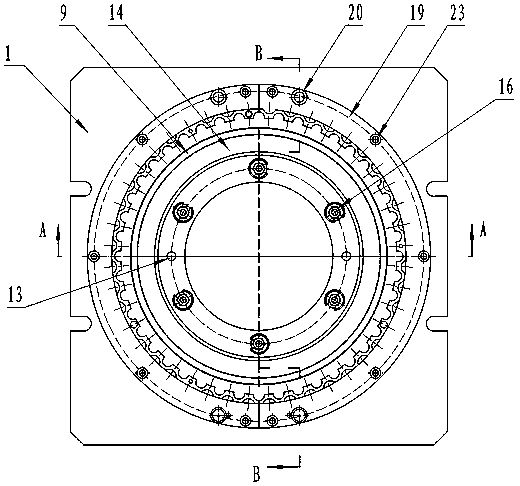
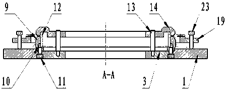
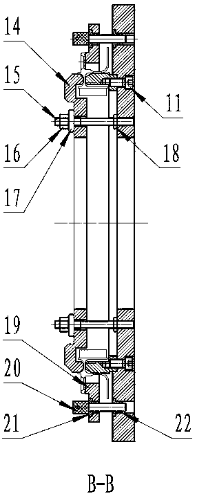
[0030] This embodiment provides an auxiliary support fixture for edge and hole processing of thin-walled parts (see Figure 1-Figure 6 ), including a fixture base 1, the fixture base 1 is rectangular, with "U"-shaped grooves at both ends, two "U"-shaped grooves on each side, and a circular through hole 2 in the center of the fixture base 1 , the position of the clamp base 1 close to the through hole 2 is provided with an annular chassis 3 with a concave edge, and the clamp base 1 is evenly provided with a stepped hole 4 and a threaded hole 5 along the upper and lower directions of the circumference...


PUM


Abstract

The invention relates to the technical field of aeronautical part machining, in particular to an auxiliary supporting clamp for thin-walled part edge and hole machining and a working method of the auxiliary supporting lamp. Supporting semi-rings are arranged on the edge part of a part, the rigidity of the thin-walled part is effectively improved, the fit clearance between the thin-walled part andthe auxiliary support is controlled, the problem that the stress of the auxiliary support and the stress of the thin-walled part are unbalanced is solved, and deformation generated after part edge and hole machining is controlled. According to the adopted technical scheme, the auxiliary supporting clamp comprises a clamp base, the two ends of the rectangular clamp base are provided with opened U-shaped grooves, the clamp base is provided with a circular ring-shaped chassis, an inner ring of the circular ring-shaped chassis is provided with a concaved platform, the concaved platform is provided with a positioning ring, the height of the positioning ring is larger than that of the circular ring-shaped chassis, the clamp base is further provided with the two symmetric semi-rings, and the semi-rings are arranged on the outer side of the circular ring-shaped chassis. The certain method is adopted to machine the thin-walled part.

Description

technical field [0001] The invention relates to the technical field of aviation parts processing, in particular to an auxiliary support fixture for edge and hole processing of thin-walled parts and a working method. Background technique [0002] Thin-walled parts are mainly used in aero-engine casings and large ring parts. Their structural characteristics are large size, thin wall, and easy deformation during processing. For parts involving edge processing and hole processing, there are many methods, but for thin-walled parts, the shape is complex and the rigidity of the processed part is very poor. The conventional positioning fixture cannot locate the edge of the part, and the edge of the part is suspended during processing. The force is not balanced, the edge of the part will be warped and deformed after processing, and the hole of the part will be sunken and deformed after processing. This conventional fixture has poor positioning reliability. The fixture cannot effectiv...

Claims


Application Information

Patent Timeline
Patent Type & Authority Applications(China)
IPC IPC(8): B23Q3/06
CPCB23Q3/065Y02P70/10
Inventor 黄强黄乔庞媛李青青
Owner 西安西航集团莱特航空制造技术有限公司
Why Eureka
Try Eureka