High-cavity precision bottle cap die of novel HALF block structure

A block structure and a new type of technology, applied in the field of high-cavity precision bottle cap molds, can solve the problems of difficulty in ensuring the flatness, parallelism, and perpendicularity of large inclined planes, the inability to effectively protect the HALF block, and the inaccurate positioning of the HLAF block. Achieve the effect of reducing the possibility of mold falling, reducing weight and easy processing accuracy

Active Publication Date: 2013-05-08
CHENGDU LIANYU PRECISION MACHINERY
View PDF3 Cites 9 Cited by
  • Summary
  • Abstract
  • Description
  • Claims
  • Application Information

AI Technical Summary

Problems solved by technology

For molds with inclined guide pillars, in addition to large dimensions, high raw material costs, and easy to cause the mold to fall, the mold must ensure that the large slider is in an accurate position every time the mold is closed. If the position of the large slider is not accurate Clamping the mold will cause the inclined guide post to break, causing damage to the mold, and may even endanger personal safety
There is a large inclined surface on the large slider. Due to the long length of the large slider, the large inclined surface is also long. It is difficult to guarantee the machining accuracy of the flatness, parallelism, and perpendicularity of the large inclined surface, and the processing cost increases.
[0004] The lateral parting of the HALF block driven by the inclined guide post is a certain improvement on the basis of the above structure, but in the end it is still unsolved. The problem of inaccurate positioning and its inability to effectively protect the weakest sharp corner of the HALF block from damage during mold operation

Method used


Image

  • High-cavity precision bottle cap die of novel HALF block structure
  • High-cavity precision bottle cap die of novel HALF block structure
  • High-cavity precision bottle cap die of novel HALF block structure

Examples


Embodiment Construction

[0021] The present invention will be further described below in conjunction with the accompanying drawings, but the protection scope of the present invention is not limited to the following description.

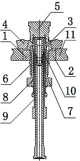
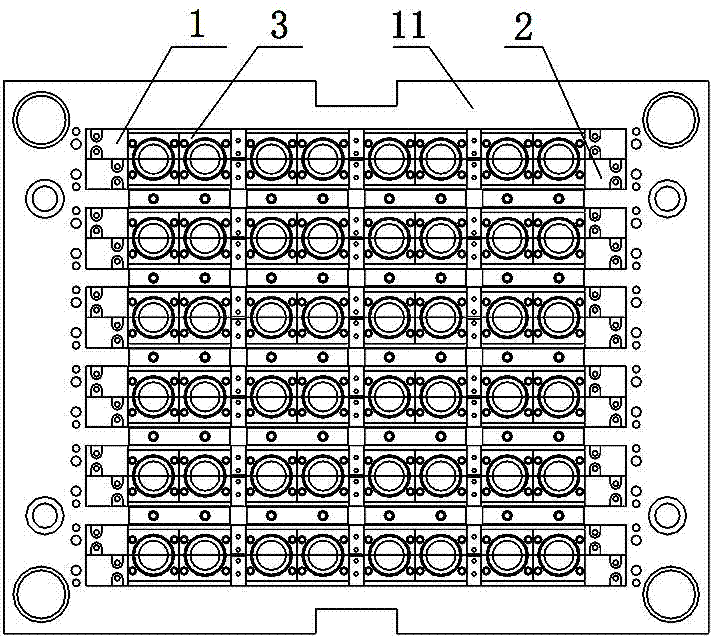
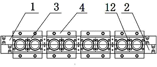
[0022] Such as figure 1 with Figure 4 As shown, the high-cavity precision bottle cap mold of the new HALF block structure includes HALF block 3, cavity 5, large slider A1, large slider B2, wedge block 4, push ring 6, thread core 7, cooling water Core 8, push tube 9 and inner core 10, the upper and lower ends of HALF block 3 are respectively provided with positioning taper holes 14 and positioning straight holes 15, both sides of HALF block 3 are provided with inclined surfaces 13, and cavity 5 is matched and installed in the positioning taper holes Inside 14, both sides of the HALF block 3 are provided with wedge tight blocks 4, the wedge tight blocks 4 are closely matched with the inclined surface 13, and the hollow push ring 6 is installed in the inside of the positioning...


PUM


Abstract

The invention relates to a high-cavity precision bottle cap die of a novel HALF block structure. The high-cavity precision bottle cap die comprises an HALF block (3), a cavity (5), a large slider A (1), a large slider B (2) and a wedge block (4), wherein a positioning taper hole and a positioning straight hole are formed on the upper and lower end faces of the HALF block (3), respectively; inclined surfaces are formed on the two sides of the HALF block (3); the cavity (5) is fitted and mounted inside the positioning taper hole; the wedge block (4) is in close fit with the inclined surfaces; a push ring (6) is fitted and mounted inside the positioning straight hole; the large slider A (1) and the large slider B (2) are arranged under the HALF block (3); a cooling water core (8) is in fit connection with a threaded core (7); a push pipe (9) is sleeved inside the cooling water core (8); and an inner core (10) is mounted inside the push pipe (9). The high-cavity precision bottle cap die is small in boundary dimension, low in manufacture cost, high in die fit precision and stable in operation, easily guaranteed in processing precision and long in service life.

Description

technical field [0001] The invention relates to the field of bottle cap injection molding, in particular to a high-cavity precision bottle cap mold with a novel HALF block structure. Background technique [0002] Traditional multi-cavity bottle cap molds use inclined guide pillars to drive sliders or HALF blocks to achieve lateral parting. [0003] The oblique guide post drives the slider to realize lateral parting by setting oblique guide post holes on the large slider, and the width of the large slider increases, which increases the width of the entire mold. Taking the 48-cavity 3025 water cover as an example, the mold is arranged in 4×12, and the large slider is relatively thin. Considering the processability, 6 cavity numbers are designed on each large slider. The distance between the two large sliders is increased, which increases the length of the entire mold. The overall dimensions of such a mold are 996mm×596mm×671mm. For molds with inclined guide pillars, in addit...

Claims


Application Information

Patent Timeline
Patent Type & Authority Applications(China)
IPC IPC(8): B29C45/26B29C33/30
Inventor 曾智张扬明
Owner CHENGDU LIANYU PRECISION MACHINERY
Why Eureka
Try Eureka