Cover pressing device

A capping, intermediate position technology, applied in packaging, flanged caps, transportation and packaging, etc., can solve problems such as work process obstruction, affecting production progress, capping deviation, etc., to achieve convenient use, ensure production progress, simple structure

Active Publication Date: 2018-08-31
张福谦
View PDF6 Cites 3 Cited by
  • Summary
  • Abstract
  • Description
  • Claims
  • Application Information

AI Technical Summary

Problems solved by technology

The crimping is a rigid contact, and the bottle cap is prone to be damaged by pressing, which will affect the production progress and cause waste of the bottle cap. When the bottle cap is clamped, the position of the cap is often not aligned, resulting in a deviation of the gland, which is harmful to the work. Process is hindered

Method used


Image

  • Cover pressing device

Examples


Embodiment Construction

[0015] The present invention will be further described below in conjunction with the description of the drawings and specific implementations:

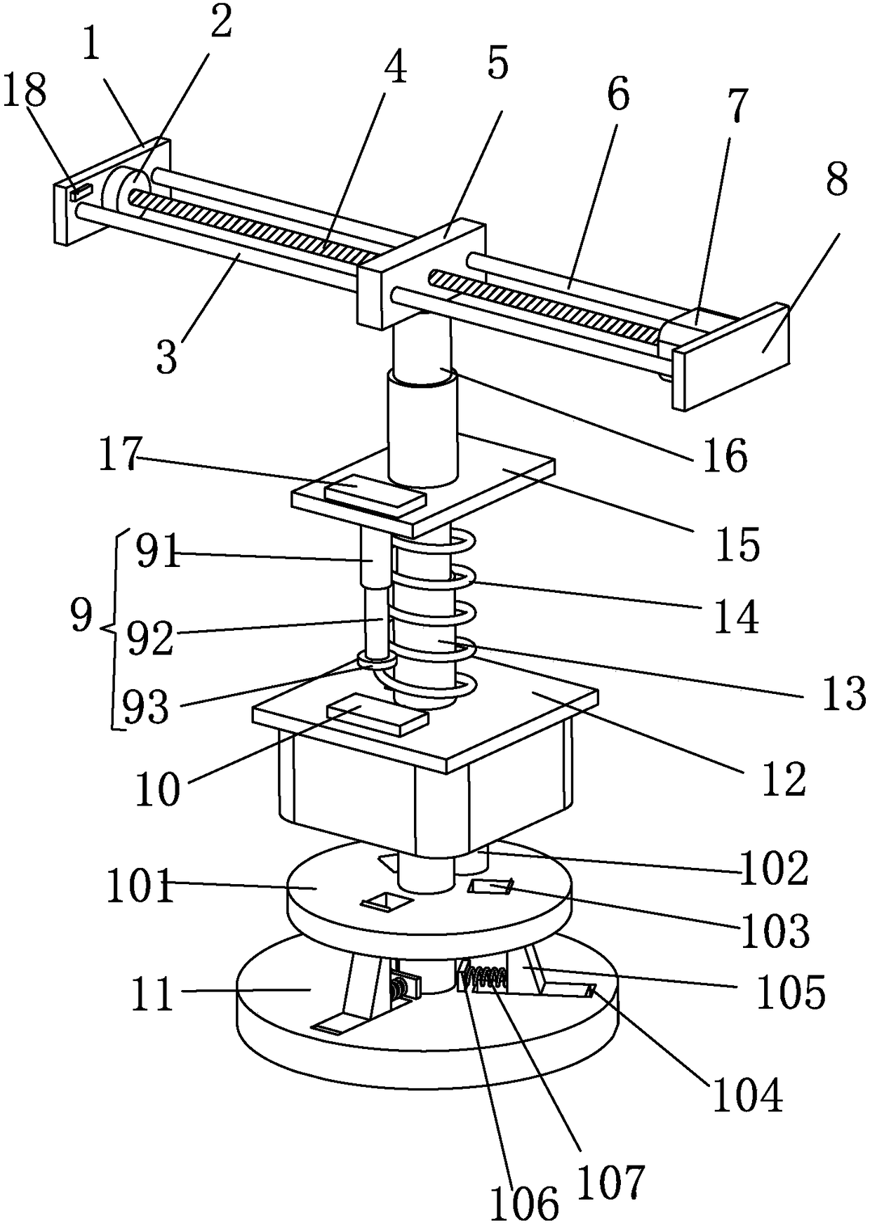
[0016] Such as figure 1 A capping device shown includes a second support plate 15, which is characterized in that the middle position of the lower surface of the second support plate 15 is fixedly connected to the upper end of the telescopic rod 13, and the lower end of the telescopic rod 13 and the first support plate The middle position of the upper surface of 12 is fixedly connected, the telescopic rod 13 is sleeved with a spring 14, the front side of the lower surface of the second support plate 15 is fixed with a limit device 9, and the middle position of the lower surface of the first support plate 12 is fixed with an electric suction cup 11 , The middle position of the upper surface of the second support plate 15 is fixedly connected to the lower end of the electric telescopic rod 16, and the upper end of the electric telescopic r...


PUM


Abstract

The invention discloses a cover pressing device which comprises a second supporting plate. The middle portion of the lower surface of the second supporting plate is fixedly connected to the upper endof a telescopic rod. The lower end of the telescopic rod is fixedly connected to the middle portion of the upper surface of a first supporting plate. The telescopic rod is connected to a spring in a sleeved mode. A limiting device is fixedly arranged on the front side of the lower surface of the second supporting plate. An electric suction cup is fixedly arranged on the middle portion of the lowersurface of the first supporting plate. The middle portion of the upper surface of the second supporting plate is fixedly connected to the lower end of the electric telescopic rod. The upper end of the electric telescopic rod is fixedly connected to the lower surface of a moving block. A bottle cover flexibly contacts the upper end of a bottle by the telescopic rod and the spring, and therefore the bottle cover is not liable to be damaged by pressing and the manufacturing schedule is guaranteed. A plurality of grippers are contracted so that the bottle cover is gradually positioned to a central position. A PLC detects the rubber pad moving by a set distance by a micro switch. The PLC controls the electric suction cup to stop working. Cover pressing of the bottle cover is convenient to detect and the structure is simple.

Description

Technical field [0001] The present invention relates to the technical field of capping, in particular to a capping device. Background technique [0002] Most of the existing capping technologies use an automatic capping machine and adopt a vertical crimping method to achieve capping. The crimping is a rigid contact, and the bottle cap is prone to be damaged by pressing, which affects the production progress and causes the waste of the bottle cap. When the bottle cap is clamped, the pressure cap is often misaligned due to the unaligned position. The process is hindered. [0003] Therefore, the existing capping device needs further improvement. Summary of the invention [0004] The purpose of the present invention is to overcome the deficiencies in the prior art and provide a capping device. [0005] In order to achieve the above objectives, the present invention adopts the following solutions: [0006] A capping device comprising a second support plate, characterized in that the midd...

Claims


Application Information

Patent Timeline
Patent Type & Authority Applications(China)
IPC IPC(8): B67B3/26B67B3/02
CPCB67B3/02B67B3/262B67B3/264B67B2201/06
Inventor 叶嘉维
Owner 张福谦
Why Eureka
Try Eureka