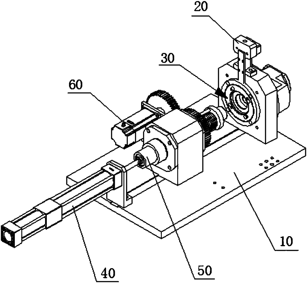
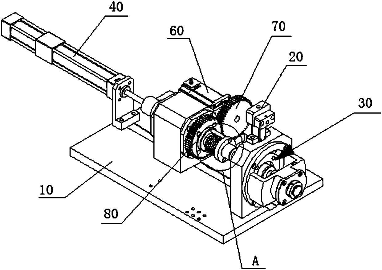
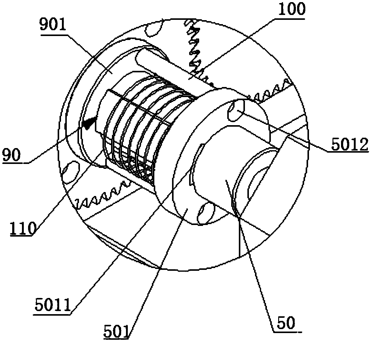
Pin mounting machine for holder

A cage and needle loading machine technology, which is applied to mechanical equipment, bearing components, shafts and bearings, etc., can solve the problems of low needle loading efficiency and low qualified rate of finished products, and achieve the effect of improving needle loading efficiency and finished product qualification rate.

Pending Publication Date: 2018-08-31
SUZHOU XINHAO BEARING
View PDF0 Cites 4 Cited by
  • Summary
  • Abstract
  • Description
  • Claims
  • Application Information

AI Technical Summary

Problems solved by technology

[0005] The purpose of the present invention is to provide a cage needle loading machine to alleviate the technical problems of low needle loading efficiency and low qualified rate of finished products existing in the cage needle loading machine in the prior art

Method used


Image

  • Pin mounting machine for holder
  • Pin mounting machine for holder
  • Pin mounting machine for holder

Examples


Embodiment Construction

[0036] The technical solutions of the present invention will be clearly and completely described below in conjunction with the accompanying drawings. Apparently, the described embodiments are some of the embodiments of the present invention, but not all of them. Based on the embodiments of the present invention, all other embodiments obtained by persons of ordinary skill in the art without making creative efforts belong to the protection scope of the present invention.

[0037] In the description of the present invention, it should be noted that the orientations or positional relationships indicated by the terms "center", "horizontal", "inner", "outer", etc. are based on the orientations or positional relationships shown in the drawings, and are only for It is convenient to describe the present invention and simplify the description, but does not indicate or imply that the device or element referred to must have a specific orientation, be constructed and operate in a specific o...


PUM


Abstract

The invention relates to the technical field of pin mounting equipment for a holder, in particular to a pin mounting machine for the holder. The pin mounting machine for the holder comprises a supporting frame, a storage hopper and a pin mounting device, wherein both the storage hopper and the pin mounting device are fixedly arranged on the supporting frame; a plurality of rolling pins can be stored in the storage hopper; a discharge end of the storage hopper communicates with a charge end of the pin mounting device; the storage device can provide rolling pins for the pin mounting device; theholder can be mounted in the pin mounting device; and the pin mounting device is used for mounting the rolling pins onto the holder. The pin mounting machine for the holder provided by the invention is high in pin mounting efficiency and is relatively high in finished product qualification rate

Description

technical field [0001] The invention relates to the technical field of needle loading equipment for cages, in particular to a cage needle loading machine. Background technique [0002] Needle roller bearings have a compact radial structure. When the inner diameter and load capacity are the same as other types of bearings, the outer diameter is the smallest. It is especially suitable for support structures with limited radial installation dimensions. Currently, needle rollers are generally installed on Inside the needle roller bearing cage. [0003] However, the existing needle loading machine is prone to the problem of missing needles in the cage. Once the problem of missing needles in the cage occurs, the cage needs to be loaded twice, which reduces the efficiency of needle loading; It often occurs that the cage is crushed, resulting in a low pass rate of the finished product and increasing the cost. [0004] To sum up, how to overcome the above-mentioned defects of the e...

Claims


Application Information

Patent Timeline
Patent Type & Authority Applications(China)
IPC IPC(8): F16C43/06
CPCF16C43/065
Inventor 黄伟达张晓阳孙电勋
Owner SUZHOU XINHAO BEARING
Why Eureka
Try Eureka