
Control valve with flow-limiting function

A technology for controlling valve and valve seat, applied in sliding valve, valve details, valve device and other directions, it can solve the problems of insufficient flow, too much flow in the water pipe, inability to effectively control the flow rate and flow rate, etc., to achieve convenient operation and ensure flow rate. Effect

Inactive Publication Date: 2018-08-31
JOHNSTON FLOW TECH WUXI CO LTD
View PDF0 Cites 1 Cited by
  • Summary
  • Abstract
  • Description
  • Claims
  • Application Information

AI Technical Summary

Problems solved by technology

[0005] Aiming at the deficiencies of the prior art, the present invention provides a control valve with a flow limiting function, which has the advantages of convenient adjustment, simple operation, and effective control of flow rate and flow rate, and solves the problem that the flow rate and flow rate cannot be effectively controlled. As a result, the required flow cannot be properly controlled, so that the flow of the water pipe is too much or the flow is not enough, which reduces the problem of efficiency

Method used


Image

  • Control valve with flow-limiting function
  • Control valve with flow-limiting function
  • Control valve with flow-limiting function

Examples


Embodiment Construction

[0022] The following will clearly and completely describe the technical solutions in the embodiments of the present invention with reference to the accompanying drawings in the embodiments of the present invention. Obviously, the described embodiments are only some, not all, embodiments of the present invention. Based on the embodiments of the present invention, all other embodiments obtained by persons of ordinary skill in the art without making creative efforts belong to the protection scope of the present invention.

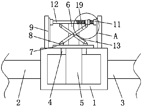
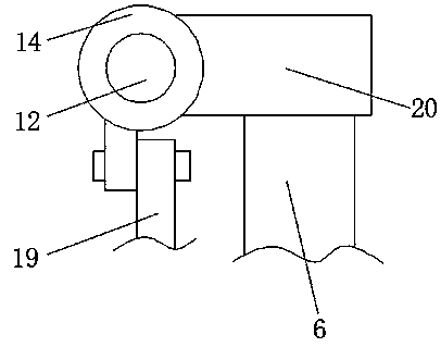
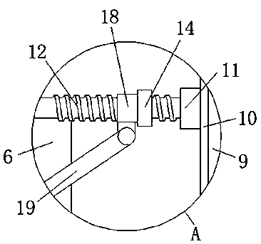
[0023] see Figure 1-4 , a control valve with a flow-limiting function, including a control valve seat 1, the left and right sides of the control valve seat 1 are respectively connected with a water inlet pipe 2 and a water outlet pipe 3, and the top of the control valve seat 1 is fixedly installed with a sealing plug 4 , can effectively seal the interface between the control valve seat 1 and the pillar 6, ensuring the tightness of the control valve seat 1 whe...


PUM


Abstract

The invention relates to the technical field of control valves, and discloses a control valve with a flow-limiting function. The control valve with the flow-limiting function comprises a control valveseat. A water inlet pipe and a water outlet pipe separately communicate with left and right sides of the control valve seat. A sealing plug is fixedly installed at the top of the control valve seat.A flow-limiting block is movably arranged in the middle of the sealing plug in a sleeving mode. The lower end of the flow-limiting block extends to the inside of the control valve seat. According to the control valve with the flow-limiting function, through an adjustment block, the movement of a sleeve ring can be effectively pushed under the action of a sliding groove and a third sliding block, the operation of staff is convenient; through a first bracket and a second bracket, the second bracket is pushed to move under the action of the adjustment block; through the first sliding block and afirst sliding rail, the height of a screw rod can be descended or risen; and a fixed plate is used for driving a supporting column to rise and descend, so that the height of the flow-limiting block iseffectively adjusted, and it is guaranteed that the flow rate is effectively adjusted.

Description

technical field [0001] The invention relates to the technical field of control valves, in particular to a control valve with a flow limiting function. Background technique [0002] The control valve is composed of two main assemblies: valve body assembly and actuator assembly (or actuator system), which are divided into four series: single-seat series control valves, double-seat series control valves, sleeve series control valves And self-operated series control valves. Variations of the four types of valves result in a myriad of different applicable configurations, each with its own specific applications, features, advantages and disadvantages. [0003] At present, the existing control valves on the market are simple in structure, and cannot effectively control the flow rate and flow rate during use, resulting in the inability to properly control the required flow rate, resulting in excessive or insufficient flow in the water pipe. , reducing the efficiency. Contents of...

Claims


Application Information

Patent Timeline
Patent Type & Authority Applications(China)
IPC IPC(8): F16K3/00F16K3/316F16K3/314F16K31/50F16K31/44
CPCF16K3/00F16K3/314F16K3/316F16K31/44F16K31/50
Inventor 钱向阳
Owner JOHNSTON FLOW TECH WUXI CO LTD
Learn More