H-bridge circuit with current limiting function

A bridge circuit and functional technology, applied in the field of H bridge circuit, can solve the problems such as difficulty in adjusting parameters, inapplicability of direct drive, small output current, etc.

Inactive Publication Date: 2019-07-05
SHENYANG INST OF AUTOMATION - CHINESE ACAD OF SCI
View PDF6 Cites 0 Cited by
  • Summary
  • Abstract
  • Description
  • Claims
  • Application Information

AI Technical Summary

Problems solved by technology

The analog driving method uses an oscillating circuit to drive piezoelectric ceramics, which is not suitable for digital controllers that need to adjust the phase and frequency. The output current of the high-voltage op-amp mode of the integrated device is small, and the high-voltage op-amp mode of the separated device has a complex structure and difficult adjustment parameters.
[0003] For some specific applications of piezoelectric ceramics or electrodes, it is necessary to precisely control the phase and frequency of the drive through a digital controller. In this case, the H-bridge circuit has great advantages, and the classic H-bridge circuit has no output current limiting function. , not suitable for direct drive of capacitive loads such as piezoelectric ceramics, therefore, an H-bridge circuit with current limiting function is required

Method used


Image

  • H-bridge circuit with current limiting function
  • H-bridge circuit with current limiting function
  • H-bridge circuit with current limiting function

Examples


Embodiment Construction

[0020] The present invention will be further described in detail below in conjunction with the accompanying drawings and embodiments.

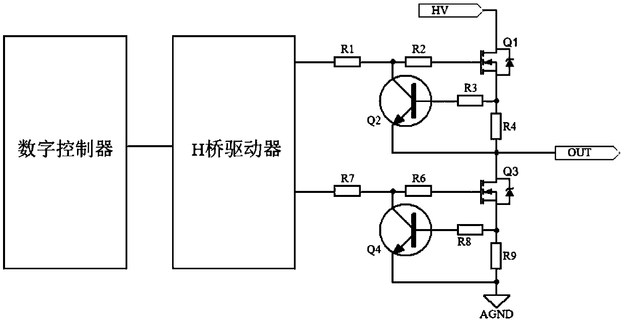
[0021] like figure 1 Shown is the block diagram of the circuit structure of the present invention.

[0022] The H-bridge drive circuit with current limiting function includes an H-bridge, an H-bridge driver, and a current-limiting unit; the H-bridge includes MOS transistors Q1, Q3, and gate resistors R1, R2, R6, and R7; the current-limiting unit includes Transistors Q2, Q4, base resistors R3, R8, and sampling resistors R4, R9; the gate resistors R1, R2, R6, and R7 can be zero; HV is the high-voltage side power supply of the H-bridge, and AGND is the high-voltage side of the H-bridge sideways.

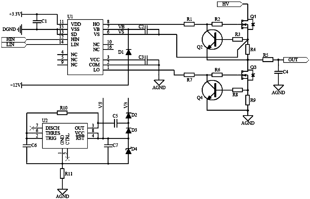
[0023] like figure 2 Shown is the circuit connection diagram of the present invention.

[0024] U1 is the H-bridge driver chip IR2110S, the digital controller is connected to U1 through the HIN and LIN interfaces, and U1 is connected to the H-bridg...


PUM


Abstract

The invention relates to the field of piezoelectric driving, the field of electrode driving and the field of constant current driving, in particular to an H-bridge circuit with a current limiting function. The H-bridge circuit comprises a digital controller connected with an H-bridge driver and used for outputting an H-bridge control signal, and the H-bridge driver is connected with an H-bridge and used for driving the H-bridge to operate. The circuit can be used for piezoelectric ceramic driving, electrode driving and constant-current driving, is simple in structure and large in output current, and has a current limiting function.

Description

technical field [0001] The invention relates to the fields of piezoelectric drive, electrode drive and constant current drive, in particular to an H-bridge circuit with current limiting function. Background technique [0002] At present, the piezoelectric drive implementation methods mainly include analog drive mode, integrated device high-voltage op-amp mode, and separated device high-voltage op-amp mode. The analog drive method uses an oscillating circuit to drive piezoelectric ceramics, which is not suitable for digital controllers that need to adjust phase and frequency. The output current of the high-voltage op-amp mode of integrated devices is small, and the high-voltage op-amp mode of discrete devices has a complex structure and difficult adjustment parameters. [0003] For some specific applications of piezoelectric ceramics or electrodes, it is necessary to precisely control the phase and frequency of the drive through a digital controller. In this case, the H-bridg...

Claims


Application Information

Patent Timeline
IPC IPC(8): H02M1/00
CPCH02M1/00H02M1/0012
Inventor 李松胡延旭郑雄飞朱慧轩王赫然王强
Owner SHENYANG INST OF AUTOMATION - CHINESE ACAD OF SCI
Why Eureka
Try Eureka