Etching electrode and edge etching device

A technology for etching devices and electrodes, which is applied to circuits, discharge tubes, electrical components, etc., can solve problems affecting production capacity, large manpower and time, and achieve the effects of reducing costs, increasing production capacity, and saving manpower and time

Active Publication Date: 2018-08-31
淮安西德工业设计有限公司
View PDF7 Cites 0 Cited by
  • Summary
  • Abstract
  • Description
  • Claims
  • Application Information

AI Technical Summary

Problems solved by technology

[0005] For different process requirements, if it is necessary to adjust different areas etched on the edge of the wafer, it is necessary to replace the shielding ring with a different diameter, which will cost a lot of manpower and time, and affect the production capacity

Method used


Image

  • Etching electrode and edge etching device
  • Etching electrode and edge etching device
  • Etching electrode and edge etching device

Examples


Embodiment Construction

[0024] The specific implementation of the etching electrode and the edge etching device provided by the present invention will be described in detail below with reference to the accompanying drawings.

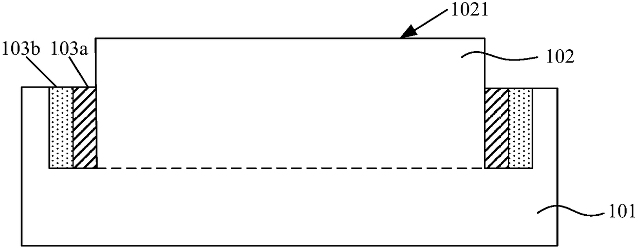
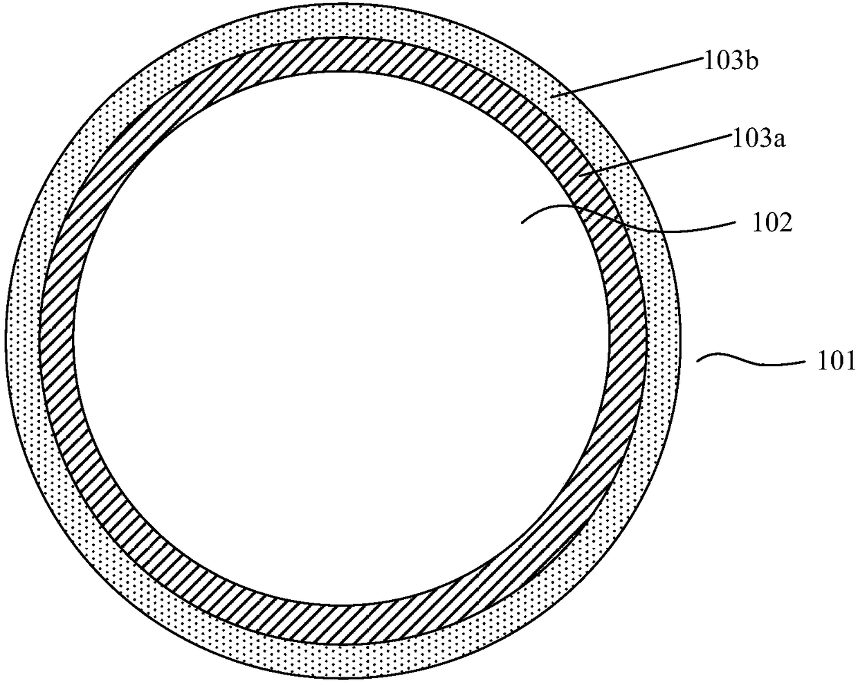
[0025] Please refer to figure 2 and image 3 , figure 2 It is a schematic cross-sectional structure diagram of an etching electrode according to a specific embodiment of the present invention; image 3 It is a schematic top view of the etched electrode.

[0026] The etching electrode includes: an electrode body, including a base 101 and a protruding electrode 102 on the base 101, the top of the protruding electrode 102 is an electrode surface 1021, and there is an annular concave hole between the base 101 and the protruding electrode 102. groove.

[0027] The etching electrode also includes at least one shielding ring, the shielding ring is arranged around the electrode body, and the at least one shielding ring is located in the annular groove. In this specific embodimen...


PUM


Abstract

The invention relates to an etching electrode and an edge etching device; the etching electrode comprises the following parts: an electrode body including a pedestal and a projection electrode arranged on the pedestal, wherein the projection electrode top is the electrode surface, and an annular groove is formed between the pedestal and the projection electrode; at least one shield ring embedded inside and outside the electrode body in an encircling manner, and the at least one shield ring is located in the annular groove; a drive unit connected with the shield ring and used for controlling each shield ring to move up and down in the direction vertical to the electrode surface, wherein in rising, the shield ring moves to the electrode surface direction, and in descending, the shield ring moves to the pedestal direction.

Description

technical field [0001] The invention relates to the technical field of semiconductors, in particular to an etching electrode and an edge etching device. Background technique [0002] The edge etching machine etches the edge of the wafer through the shielding of the wafer by the upper and lower electrodes. The etching shielding ring (PEZ Ring) surrounds the upper and lower electrodes, and the etching range is controlled by selecting shielding rings with different diameters. The larger the diameter of the shielding ring, the smaller the area etched at the edge. [0003] Please refer to figure 1 , is a schematic diagram of an edge etching device in the prior art. [0004] The upper electrode 10 and the lower electrode 20 respectively cover the upper and lower surfaces of the wafer 30 , the shielding ring 11 surrounds the upper electrode 10 , and the shielding ring 21 surrounds the lower electrode 20 so that the plasma 31 can etch the edge of the wafer 30 . By adjusting the d...

Claims


Application Information

Patent Timeline
Patent Type & Authority Applications(China)
IPC IPC(8): H01J37/32
CPCH01J37/32633
Inventor 梁倪萍陈伏宏刘家桦
Owner 淮安西德工业设计有限公司
Why Eureka
Try Eureka