
Rotor of permanent magnet motor

A permanent magnet motor and rotor technology, applied in the direction of magnetic circuit rotating parts, magnetic circuit, electrical components, etc., can solve the problems of high price, easy to fall off, etc., to improve performance, improve torque coefficient, easy and reliable installation and fixation Effect

Inactive Publication Date: 2018-08-31
孙建林
View PDF0 Cites 0 Cited by
  • Summary
  • Abstract
  • Description
  • Claims
  • Application Information

AI Technical Summary

Problems solved by technology

[0004] The current magnetic steel is pasted on the rotating shaft in pieces, which is expensive, and it is easy to fall off after a long time running, so it needs to be improved

Method used


Image

  • Rotor of permanent magnet motor
  • Rotor of permanent magnet motor
  • Rotor of permanent magnet motor

Examples


Embodiment Construction

[0033] The present invention will be further described below in conjunction with accompanying drawing and specific embodiment:

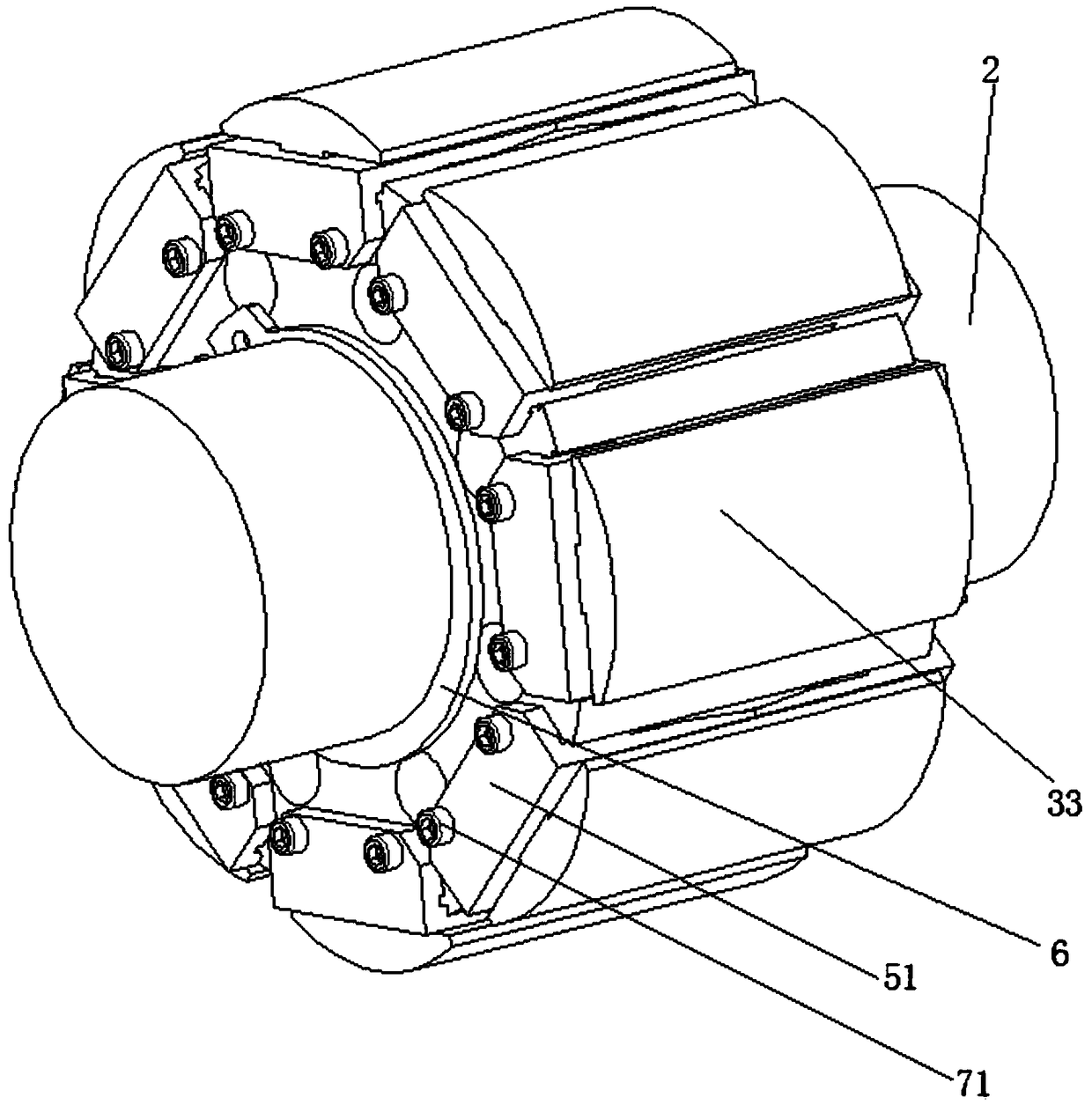
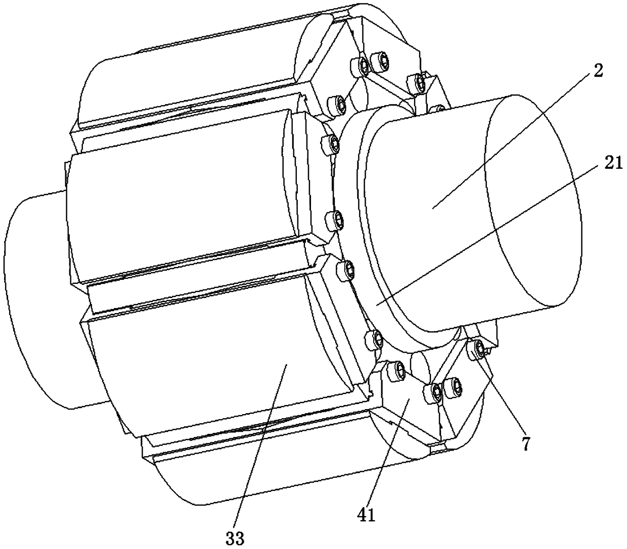
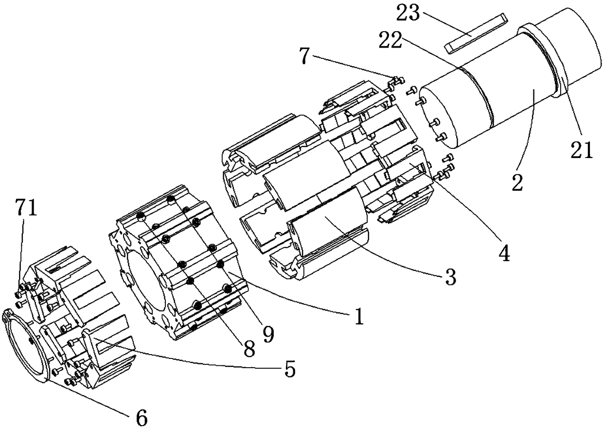
[0034] Such as Figure 1 to Figure 16 As shown, a permanent magnet motor rotor includes a rotor core 1, a shaft 2, a magnetic steel 3, a front baffle 4 and a rear baffle 5, and the center of the rotor core 1 is provided with a shaft 2 that is tightly fitted and pressed into it. The shaft hole 14, the outer edge of the rotor core 1 is evenly distributed in the circumferential direction and the magnetic steel groove 11 runs through the front and rear. The outer edge of the rotor iron core 1 is located on the upper end of the magnetic steel groove 11. The left and right sides are symmetrically provided with pressing tables 12. The pressing table 12 runs through the front and rear end faces of the rotor core 1. Two pin slots 13 are provided at the junction of the press table 12 and the magnetic steel slot 11 on each side, and the press table 12 is provid...


PUM


Abstract

The invention discloses a rotor of a permanent magnet motor. The rotor comprises a rotor iron core, a shaft, magnetic steel, a front baffle and a rear baffle, wherein the center of the rotor iron coreis provided with a shaft hole allowing the shaft to be tightly pressed into the shaft hole, magnetic steel grooves are evenly formed in the circumferential direction of the outer edge of the rotor iron core, and pressing tables are symmetrically arranged at the positions, on the left side and right side of the upper end of the magnetic steel grooves, on the outer edge of the rotor iron core; a pin groove is formed in the boundary of the pressing table on each side and the corresponding magnetic steel groove; pins are tightly pressed into the pin grooves, springs are inserted in the pins, andthe magnetic steel is arranged in the magnetic steel grooves and comprises inner magnetic steel parts, square connecting parts and outer magnetic steel parts; the outer walls of the two sides of eachinner magnetic steel part are both provided with two semicircular notches, the counter of the semicircular notches is matched with that of the outer walls of the pins, and each inner magnetic steel part is tightly pressed into and attached to the bottom face of the corresponding magnetic steel groove along four pins; the upper end faces of the inner magnetic steel parts are flush with the pressingtables, and the upper end faces of the inner magnetic steel parts are in pressed connection through the front baffle and the rear baffle. The magnetic steel is convenient and reliable to install andfix, the cost is low, and the performance of the motor is improved.

Description

technical field [0001] The invention relates to the field of motor rotors, in particular to a permanent magnet motor rotor. Background technique [0002] With the continuous improvement of the performance of permanent magnet materials and the development of motor technology, permanent magnet motors have been widely used in various fields of the national economy, and permanent magnet rotors are an important part of permanent magnet motors. [0003] The magnetic steel of the permanent magnet rotor is mainly divided into two types: surface mount type and built-in type. Compared with the built-in permanent magnet rotor, the surface-mounted permanent magnet rotor has a small field-weakening speed regulation range and low power density, but it has the characteristics of fast dynamic response and small torque ripple, and is suitable for servo drive. The built-in permanent magnet rotor superimposes the reluctance torque on the basis of the permanent magnet torque. The existence of ...

Claims


Application Information

Patent Timeline
Patent Type & Authority Applications(China)
IPC IPC(8): H02K1/27
CPCH02K1/2706
Inventor 孙建林
Owner 孙建林
Features
  • Generate Ideas
  • Intellectual Property
  • Life Sciences
  • Materials
  • Tech Scout
  • Unparalleled Data Quality
  • Higher Quality Content
  • 60% Fewer Hallucinations
Learn More