Stator core, motor and compressor

A stator core and stator technology is applied in the field of compressors, which can solve the problems of limited busbar voltage and the inability to increase the back EMF coefficient without limit, and achieve the effect of improving the torque and torque coefficient of the motor.

Inactive Publication Date: 2018-11-06
GUANGDONG WELLING AUTO PARTS CO LTD
View PDF5 Cites 14 Cited by
  • Summary
  • Abstract
  • Description
  • Claims
  • Application Information

AI Technical Summary

Problems solved by technology

According to the motor design theory, under the premise of a certain speed, the torque coefficient of the motor increases, and the overload capacity and efficiency of the motor will also increase. However, due to the same motor, the torque coefficient is proportional to the back EMF coefficient, which is limited by the bus voltage. , when increasing the torque coefficient, the back EMF coefficient cannot be increased without limit, so it is necessary to find a method to improve the motor torque coefficient without increasing the back EMF coefficient too high

Method used


Image

  • Stator core, motor and compressor
  • Stator core, motor and compressor
  • Stator core, motor and compressor

Examples


Embodiment

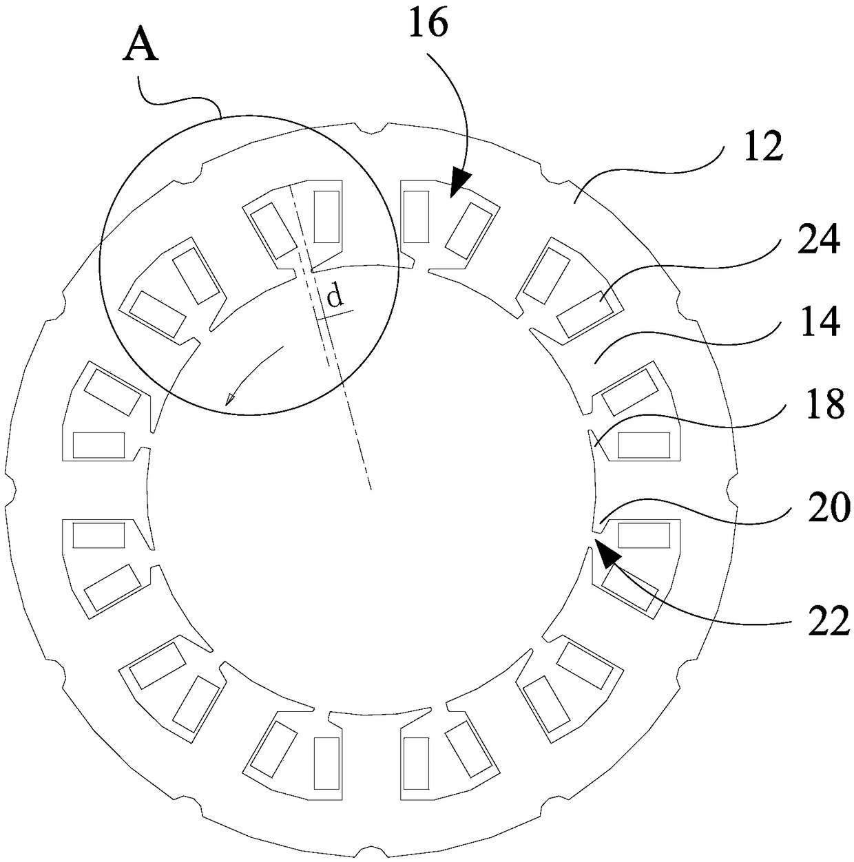
[0074] Figure 7 In the case of the same current, the output torque comparison chart of the motor. Specifically, the same eight-pole rotor is used to match the existing embodiment and the figure 1 With the stator core shown, calculate the output torque of the motor at different rotor positions. From Figure 7 It can be seen that whether it is the torque when the rotor position angle is 0°, or the maximum torque that changes with the torque position angle. Adopt the embodiment of the present invention, namely figure 1 Compared with the conventional example, the output torque of the stator core shown is significantly improved.

[0075] Figure 8 In the case of the same current, the iron loss comparison chart of the motor. Specifically, the same eight-pole rotor is used to match the existing embodiment and the figure 1 For the stator core shown, calculate the iron loss of the motor at different rotor positions. From Figure 8 It can be seen that whether it is the iron lo...


PUM


Abstract

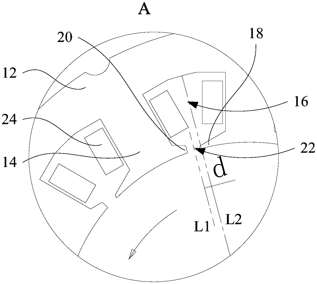
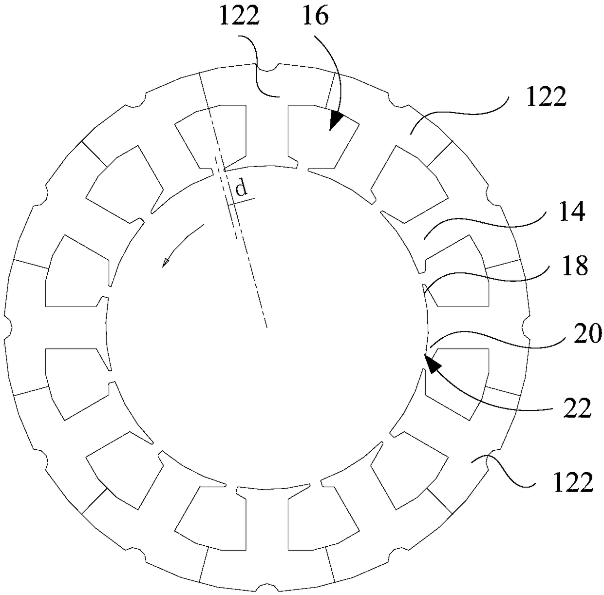
The invention provides a stator core, a motor and a compressor. A stator body is in a cylindrical shape, stator convex teeth are arranged at intervals along a circumferential direction of the stator body, a stator groove gap is limited by arbitrary two adjacent stator convex teeth, a first pole shoe and a second pole shoe both are arranged at one end, far away from the stator body, of each of theplurality of stator convex teeth and are respectively arranged at two sides of the stator convex pole teeth, the first pole shoe and the second pole shoe which are arranged at two sides of the statorgroove gap form a groove opening, a central line of adjacent stator groove gap is parallel to a central line of the groove opening, and preset distance is kept between the central line of adjacent stator groove gap and the central line of the groove opening. The preset distance is kept between the center of the groove opening and the central line of the stator groove gap, thus, reluctance torque caused by asymmetry of a rotor magnetic path structure is fully utilized, the torque and the torque coefficient of the motor can be improved by increasing the reluctance torque under the condition thata counter potential coefficient is not changed, and the motor is further enabled to have relatively high torque output capability during rotation.

Description

technical field [0001] The invention relates to the field of motors, and more specifically, to a stator core, a motor and a compressor. Background technique [0002] At present, due to the trend of miniaturization of the motor, the efficiency of the motor at the rated point should be improved as much as possible. At the same time, due to the requirements of the motor usage scenarios (such as the requirements for the compressor in the air conditioning system), the compressor should have as high an overload as possible. Capability, that is, to ensure that the motor can have a large torque output capability at high speed. According to the motor design theory, under the premise of a certain speed, the torque coefficient of the motor increases, and the overload capacity and efficiency of the motor will also increase. However, due to the same motor, the torque coefficient is proportional to the back EMF coefficient, which is limited by the bus voltage. , when the torque coefficie...

Claims


Application Information

Patent Timeline
Patent Type & Authority Applications(China)
IPC IPC(8): H02K1/14
CPCH02K1/146H02K2213/03
Inventor 孙国伟郑军洪陈汉锡虞阳波
Owner GUANGDONG WELLING AUTO PARTS CO LTD
Why Eureka
Try Eureka