Permanent magnet motor rotor and manufacturing method thereof

A technology of permanent magnet motor and manufacturing method, which is applied in the direction of magnetic circuit rotating parts, manufacturing stator/rotor body, magnetic circuit shape/style/structure, etc., which can solve the problem that the principle of compressor cannot meet the requirements and the output of cooling capacity cannot be realized , frequent start-up and high noise, etc., to improve production operability, prevent punching deformation, and improve efficiency

Active Publication Date: 2014-01-29
WHIRLPOOL CHINA
View PDF7 Cites 4 Cited by
  • Summary
  • Abstract
  • Description
  • Claims
  • Application Information

AI Technical Summary

Problems solved by technology

The speed of this kind of single-phase asynchronous motor cannot be adjusted, and the output of cooling capacity cannot be realized, and the frequent startup noise is large and the system efficiency is low
With the improvement of the country's energy efficiency standards for refrigerators and the further improvement of consumers' performance requirements for refrigerators such as rapid cooling and precise temperature control to keep fresh, traditional compressors using single-phase asynchronous motors have been unable to meet the requirements in principle.

Method used


Image

  • Permanent magnet motor rotor and manufacturing method thereof
  • Permanent magnet motor rotor and manufacturing method thereof
  • Permanent magnet motor rotor and manufacturing method thereof

Examples


Embodiment Construction

[0027] The present invention will be further described below in conjunction with accompanying drawing:

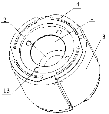
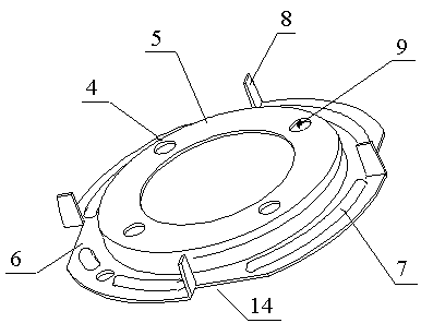
[0028] Such as figure 1 , figure 2 A permanent magnet motor rotor shown includes a rotor core and a magnetic steel 3 . The magnetic steel 3 is fixed on the outer circumference of the rotor iron core, and rotor end covers 4 are fixedly connected to both ends of the rotor iron core. Specifically, both ends of the rotor core are provided with installation holes 13 for fixed connection with the rotor end cover 4, and the rotor end cover 4 is provided with installation holes 9 for fixed connection with the rotor core, and the rotor core is connected to the rotor through rivets. The end cap 4 is fixedly connected.

[0029] Further, the rotor core is formed by laminating the punched first punching sheet 1 and the second punching sheet 2 . The first punching piece 1 and the second punching piece 2 have installation holes with different apertures, and the installation holes wit...


PUM


Abstract

The invention relates to a permanent magnet motor rotor and a manufacturing method thereof. The permanent magnet motor rotor comprises a rotor core and magnetic steel fixed to the outer circumference of the rotor core. Rotor end covers are fixedly connected with the two ends of the rotor core. The rotor core is formed by first stamped steel and second stamped steel in a laminated mode, and the first stamped steel and the second stamped steel are manufactured in a punched mode. Each rotor end cover comprises an end plate and a magnetic steel positioning part fixedly connected with the end plate, each magnetic steel positioning part is arranged on the outer circumference of the corresponding end plate and fixedly provided with bosses used for identifying the axial position of magnetic steel and positioning ribs used for positioning the radial position of the magnetic steel, and the bosses and the positioning ribs are uniformly distributed on the circumferences of the magnetic steel positioning parts. The permanent magnet motor rotor is adopted for a freezer compressor, so that the rotor speed can be adjusted at will, refrigerating capacity of the compressor can be output, and the purposes of rapid refrigeration and low-speed refreshment of a freezer can be achieved. The permanent magnet motor rotor has the advantages of being high in efficiency, low in noise, suitable for volume production and the like.

Description

technical field [0001] The invention relates to the technical field of motors, in particular to a permanent magnet motor rotor and a manufacturing method thereof. Background technique [0002] At present, refrigerator compressor motors are basically single-phase asynchronous motors, and their motor rotors are aluminum bar squirrel cage rotors. Firstly, the stator of the motor generates a rotating magnetic field; secondly, the aluminum strip on the rotor closely follows the rotating magnetic field to generate an induced current, and the direction of the current is perpendicular to the direction of the rotating magnetic steel; thirdly, the aluminum strip generates a force following the rotating magnetic field, driving the rotor to the magnetic steel The direction of rotation turns. The speed of this single-phase asynchronous motor cannot be adjusted, and cooling capacity output cannot be realized, and the frequent startup noise is large and the system efficiency is low. With...

Claims


Application Information

Patent Timeline
Patent Type & Authority Applications(China)
IPC IPC(8): H02K1/27H02K15/03
Inventor 金友华许平建丁洪涛
Owner WHIRLPOOL CHINA
Why Eureka
Try Eureka