
Magnetic steel fixing structure for permanent magnet rotor

A permanent magnet rotor and fixed structure technology, applied in the field of motor parts, can solve the problems of high price and easy falling off, and achieve the effects of low cost, improved performance, and convenient installation and positioning

Inactive Publication Date: 2018-09-04
孙建林
View PDF0 Cites 2 Cited by
  • Summary
  • Abstract
  • Description
  • Claims
  • Application Information

AI Technical Summary

Problems solved by technology

[0004] The current magnetic steel is pasted on the rotating shaft in pieces, which is expensive, and it is easy to fall off after a long time running, so it needs to be improved

Method used


Image

  • Magnetic steel fixing structure for permanent magnet rotor
  • Magnetic steel fixing structure for permanent magnet rotor
  • Magnetic steel fixing structure for permanent magnet rotor

Examples


Embodiment Construction

[0030] The present invention will be further described below in conjunction with accompanying drawing and specific embodiment:

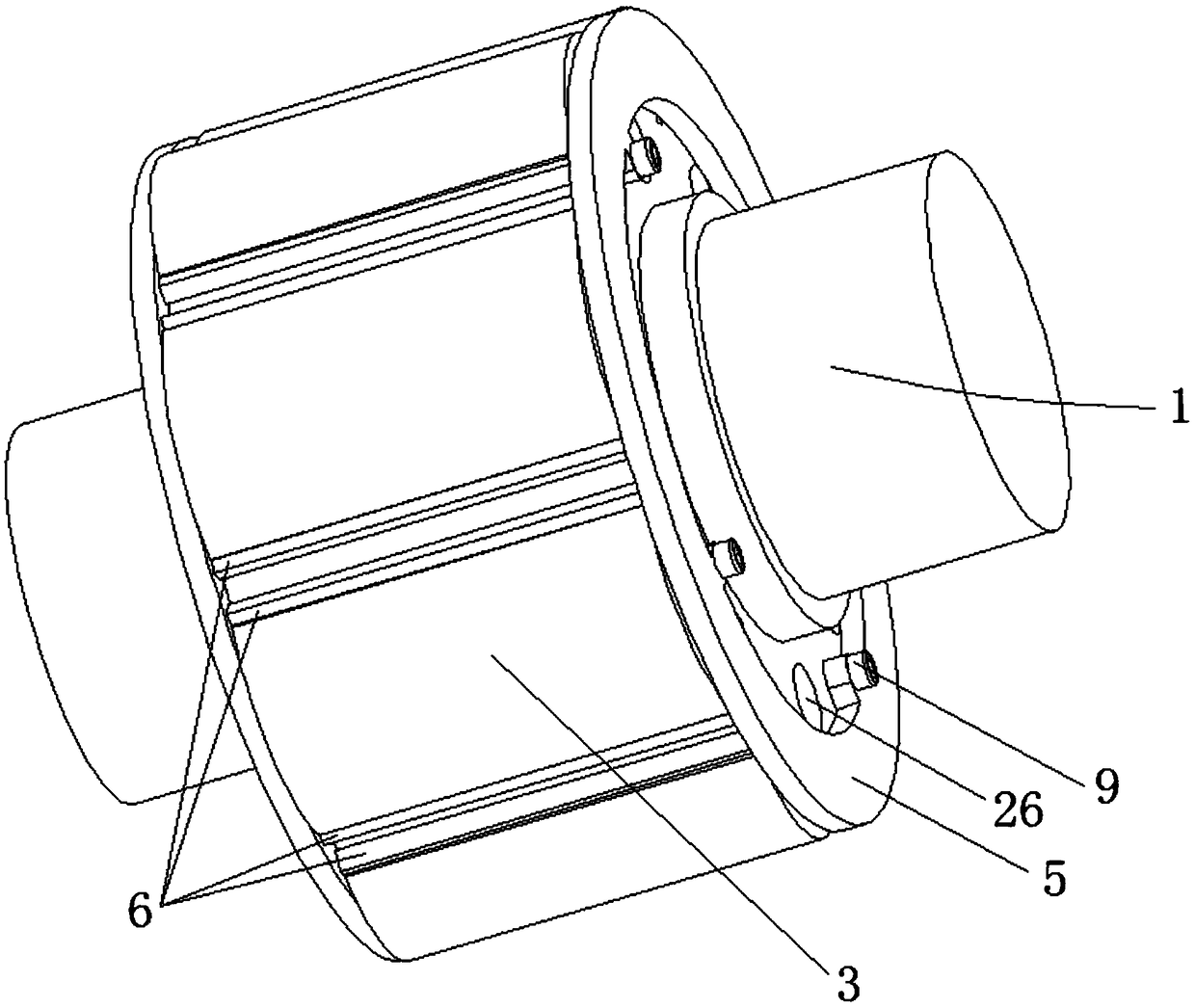
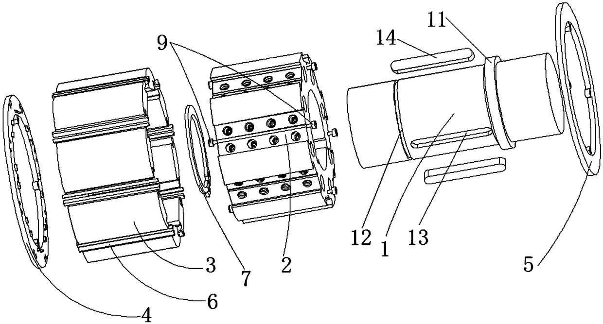
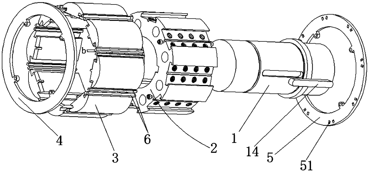
[0031] Such as Figure 1 to Figure 14 As shown, a magnetic steel fixing structure of a permanent magnet rotor includes a shaft 1, a rotor core 2 sleeved on the outer wall of the shaft 1, and a magnetic steel 3 evenly distributed on the rotor core 2, the shaft 1 The outer wall and the inner wall of the rotor core 2 are connected by a key 14, the outer wall of the shaft 1 is provided with a first keyway 13, the inner wall of the rotor core 2 is provided with a second keyway 24, and the first keyway 13 and The second key groove 24 cooperates to form a space for the insertion of the key 14, so that the rotation of the shaft 1 drives the rotor core 2 to rotate together. The number of the keys 14 is two and distributed at 120 degrees, which ensures the transmission of torque without reducing the shaft 1. The intensity of (relative to the situation that tw...


PUM


Abstract

The invention discloses a magnetic steel fixing structure for a permanent magnet rotor. The magnetic steel fixing structure comprises a shaft, a rotor iron core and magnetic steel, wherein the shaft and the rotor iron core are connected through a key, magnetic steel slots are uniformly formed in the outer wall of the rotor iron core, spring holes are formed in the bottoms of the magnetic steel slots, propping heads which extend into the magnetic steel slots are arranged on the outer wall, above the magnetic steel slots, of the rotor iron core, and magnetic steel is inserted into the magnetic steel slots; the magnetic steel comprises inner magnetic steel piece parts, square connecting parts and outer magnetic steel piece parts, the inner magnetic steel piece parts are inserted into the magnetic steel slots, and the outer magnetic steel piece parts are located on the periphery of the outer wall of the rotor iron core; and springs are arranged in the spring holes and prop against the inner magnetic steel piece parts, a front baffle is laminated to the front end surface of the rotor iron core, front positioning slots are uniformed in the circumference of the rear end surface of the front baffle, a rear baffle is laminated to the rear end surface of the magnetic steel, rear positioning slots are uniformed in the circumference of the front end surface of the rear baffle, and the front positioning slots and the rear positioning slots are connected in a one-to-one correspondence manner through partition strips. The magnetic steel fixing structure is convenient and rapid to mount, low in cost and good in reliability, and the motor performance is improved.

Description

technical field [0001] The invention relates to the field of motor parts, in particular to a magnetic steel fixing structure of a permanent magnet rotor. Background technique [0002] With the continuous improvement of the performance of permanent magnet materials and the development of motor technology, permanent magnet motors have been widely used in various fields of the national economy, and permanent magnet rotors are an important part of permanent magnet motors. [0003] The magnetic steel of the permanent magnet rotor is mainly divided into two types: surface mount type and built-in type. Compared with the built-in permanent magnet rotor, the surface-mounted permanent magnet rotor has a small field-weakening speed regulation range and low power density, but it has the characteristics of fast dynamic response and small torque ripple, and is suitable for servo drive. The built-in permanent magnet rotor superimposes the reluctance torque on the basis of the permanent ma...

Claims


Application Information

Patent Timeline
Patent Type & Authority Applications(China)
IPC IPC(8): H02K1/27
CPCH02K1/276
Inventor 孙建林
Owner 孙建林
Features
  • Generate Ideas
  • Intellectual Property
  • Life Sciences
  • Materials
  • Tech Scout
  • Unparalleled Data Quality
  • Higher Quality Content
  • 60% Fewer Hallucinations
Learn More