
Method for the representation of a rear outer region of a vehicle

An external area, area technology, applied in the field of computer program products, can solve problems such as hindering safety, and achieve the effect of ensuring detection and display

Active Publication Date: 2018-08-31
HUF HULSBECK & FURST GMBH & CO KG
View PDF6 Cites 0 Cited by
  • Summary
  • Abstract
  • Description
  • Claims
  • Application Information

AI Technical Summary

Problems solved by technology

Therefore, depending on where the camera is set, providing image information may also impede safety while driving

Method used


Image

  • Method for the representation of a rear outer region of a vehicle
  • Method for the representation of a rear outer region of a vehicle
  • Method for the representation of a rear outer region of a vehicle

Examples


Embodiment Construction

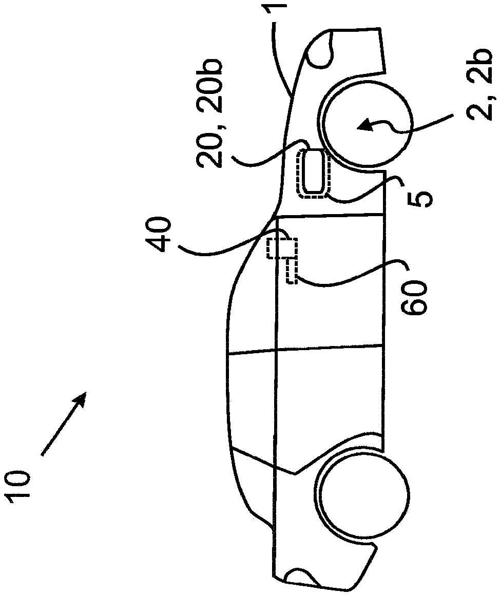
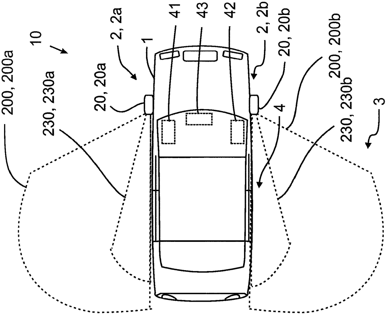
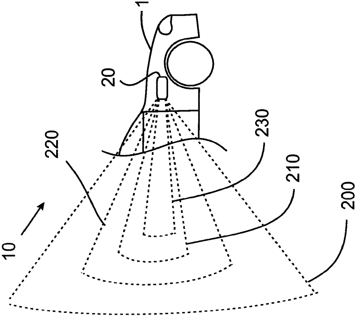
[0051] figure 1 A system 10 according to the invention is schematically shown in , which is arranged on a vehicle 1 . The system 10 according to the invention here includes at least one camera device 20 . Apart from figure 1 In addition to the second camera device 20b arranged on the right side of the vehicle 1 shown in , figure 2 The first camera device 20 a shown in FIG. 1 can also be arranged on the left side of the vehicle 1 . In this case, the first camera device 20a is preferably arranged on the left fender 2a and the second camera device 20b is arranged on the right fender 2b. Obviously, instead of the arrangement of the camera device 20 on the fender 2 , the camera device 20 can also be arranged in other regions in the front region of the vehicle 1 . For the arrangement, the vehicle 1 has, in particular, a receptacle 5 . In particular a display device 40 is arranged in the vehicle interior of the vehicle 1 . Furthermore, vehicle 1 includes a control unit 60 whic...


PUM


Abstract

The invention relates to a method (100) for the representation of a rear outer region (3) of a vehicle (1), comprising at least one camera device (20) on the vehicle (1), wherein the camera device (20) can be brought into different camera settings (240), and wherein different recording areas (220) of the outer region (3), which depend on the camera settings, can be detected in each case by the camera device (20) as a function of the camera settings (240).

Description

technical field [0001] The invention relates to a method of the type defined in the preamble of claim 1 for displaying a rearward-facing outer region of a vehicle. Furthermore, the invention relates to a system, a camera device and a computer program product for displaying a rearwardly directed outer area of ​​a vehicle of the type defined in the preamble of claim 13 . Background technique [0002] It is known from the prior art to use one or more camera devices on the vehicle to detect the area outside the vehicle. The camera system provides image information about the outside area, which can be used to improve and / or expand the field of view of the driver of the vehicle. It is thus possible, for example, to display image information from a rear camera on a monitor in the vehicle interior when the vehicle is parked in reverse gear. [0003] However, known camera systems in vehicles are generally only usable in very limited situations, such as parking. Furthermore, it has...

Claims


Application Information

Patent Timeline
Patent Type & Authority Applications(China)
IPC IPC(8): B60R1/00H04N23/90
CPCB60R2300/101B60R2300/8046B60K35/22B60K2360/21B60K35/81B60R1/28B60R1/26G06V20/56H04N23/90H04N23/695B60K35/00B60R11/04B60R2011/004B60R2300/105B60R2300/802G09G3/3208
Inventor 贝特霍尔德·许斯勒马尔科·罗森鲍姆格尔德·布施曼
Owner HUF HULSBECK & FURST GMBH & CO KG
Learn More