Connector

A connector and contact technology, which is applied in the direction of connection, two-part connection device, and parts of the connection device, can solve the problems of insufficient protection against negative electrical influences such as crosstalk, narrow spacing, etc., to avoid negative electrical influences, suppress The effect of crosstalk

Active Publication Date: 2018-08-31
HIROSE ELECTRIC GROUP
View PDF7 Cites 2 Cited by
  • Summary
  • Abstract
  • Description
  • Claims
  • Application Information

AI Technical Summary

Problems solved by technology

[0006] However, in order to secure the circuit wiring space on the board, etc., in the case of downsizing the board-side connector mounted on the board, the distance between one terminal group and the other terminal group of the insulating case is maintained. becomes narrower, so it is difficult to reduce or avoid electrical negative effects such as crosstalk generated between the above-mentioned terminal groups
For example, in the co

Method used


Image

  • Connector
  • Connector
  • Connector

Examples


Embodiment Construction

[0048] Embodiments of the present invention will be described below with reference to the drawings. In addition, in all the drawings for explaining the embodiment, in principle, the same reference numerals are assigned to the same components, and repeated description thereof will be omitted. In addition, although each embodiment is demonstrated independently, it does not exclude that a connector is comprised by combining the structural elements of each other.

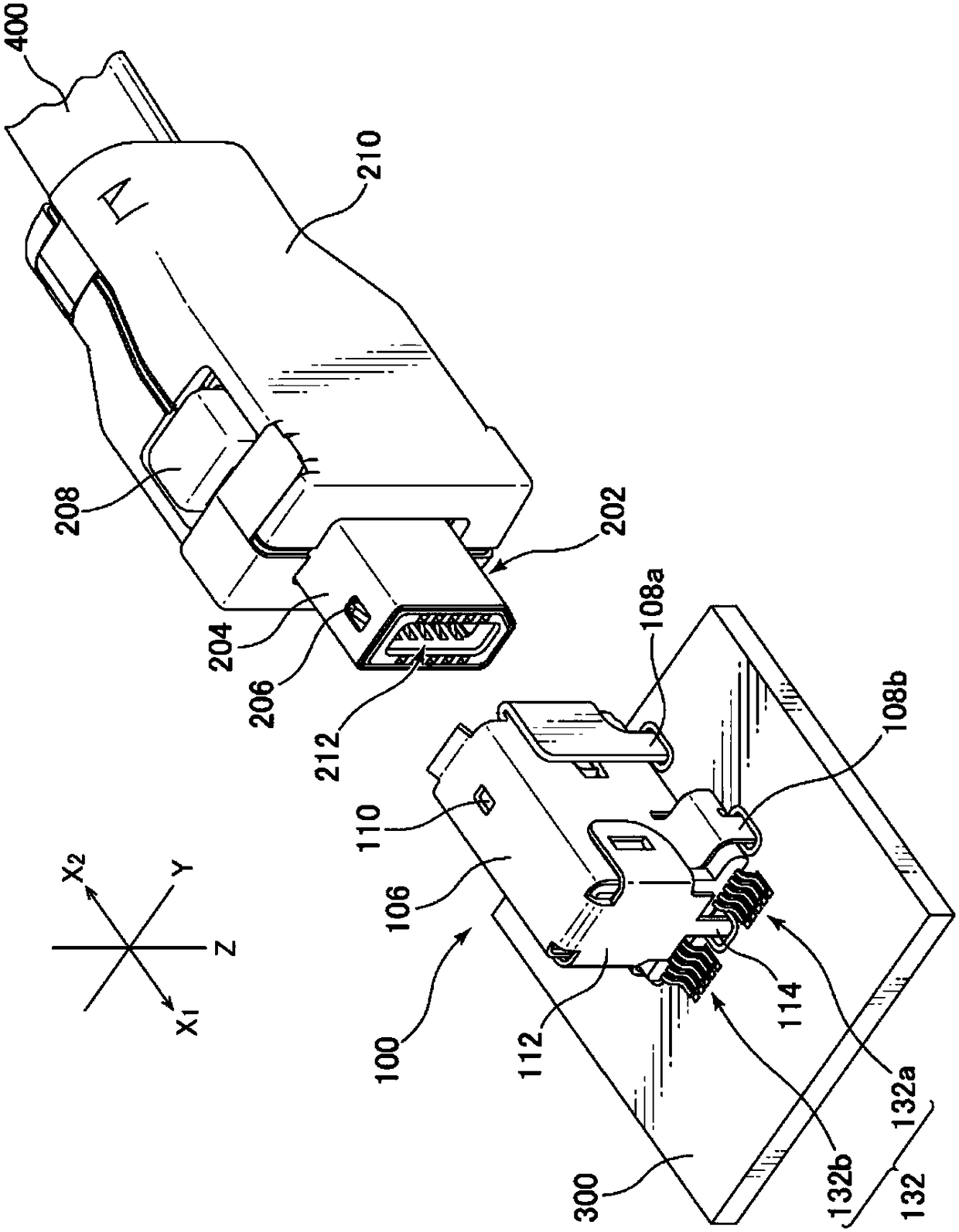
[0049] figure 1 It is a diagram showing the appearance of the connector on the board side and the connector on the cable side. The fitting direction of the connector is the X1-X2 direction (X-axis direction) in the figure. The front end side of the board-side connector 100 is the X2 direction side, and the front end side of the cable-side connector 200 is the X1 direction side. A plane perpendicular to the substrate 300 is an XZ plane, and a plane (parallel plane) to the substrate 300 is an XY plane. The upper and l...


PUM


Abstract

When the size of a substrate-side connector mounted upon a substrate is reduced in order to ensure circuit wiring space upon the substrate, the spacing between one terminal group and another terminalgroup that are retained in an insulated housing within an external conductor shell of the connector becomes even narrower, and thus a technical problem can arise wherein it becomes difficult to reduceor avoid adverse electrical effects such as crosstalk occurring between the terminal groups. In order to solve this problem, the present invention provides a connector in which a housing (150) is composed separately of a first housing member (150a) for retaining a first terminal group and a second housing member (150b) for retaining a second terminal group, an accommodating section (172, 174) foraccommodating a conductive member plate (160) is provided in at least one of the surfaces (joining surfaces) joining the first and second housing members (150a, b), and the conductive plate (160) electrically separates the first terminal group and the second terminal group, thereby making it possible to suppress the occurrence of crosstalk and reduce or avoid adverse electrical effects on high frequency characteristics.

Description


Claims


Application Information

Patent Timeline
Owner HIROSE ELECTRIC GROUP
Why Eureka
Try Eureka