Brazier type stone simmer electric barbeque oven
A technology for barbecue ovens and braziers, which is applied to baking devices, household utensils, applications, etc., can solve the problems of complex structure, difficulty in maintaining heat for a long time, and bulky volume, and achieve the goal of reducing operation difficulty, improving barbecue efficiency, and increasing rotation function Effect
- Summary
- Abstract
- Description
- Claims
- Application Information
AI Technical Summary
Problems solved by technology
Method used
Image
Examples
Embodiment 1
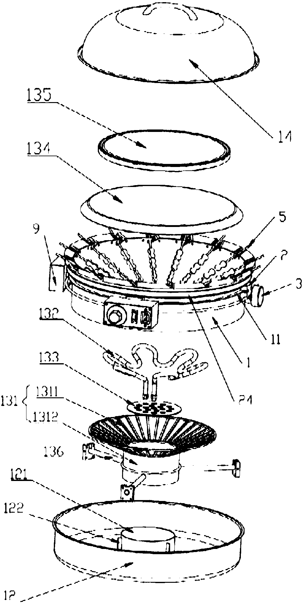
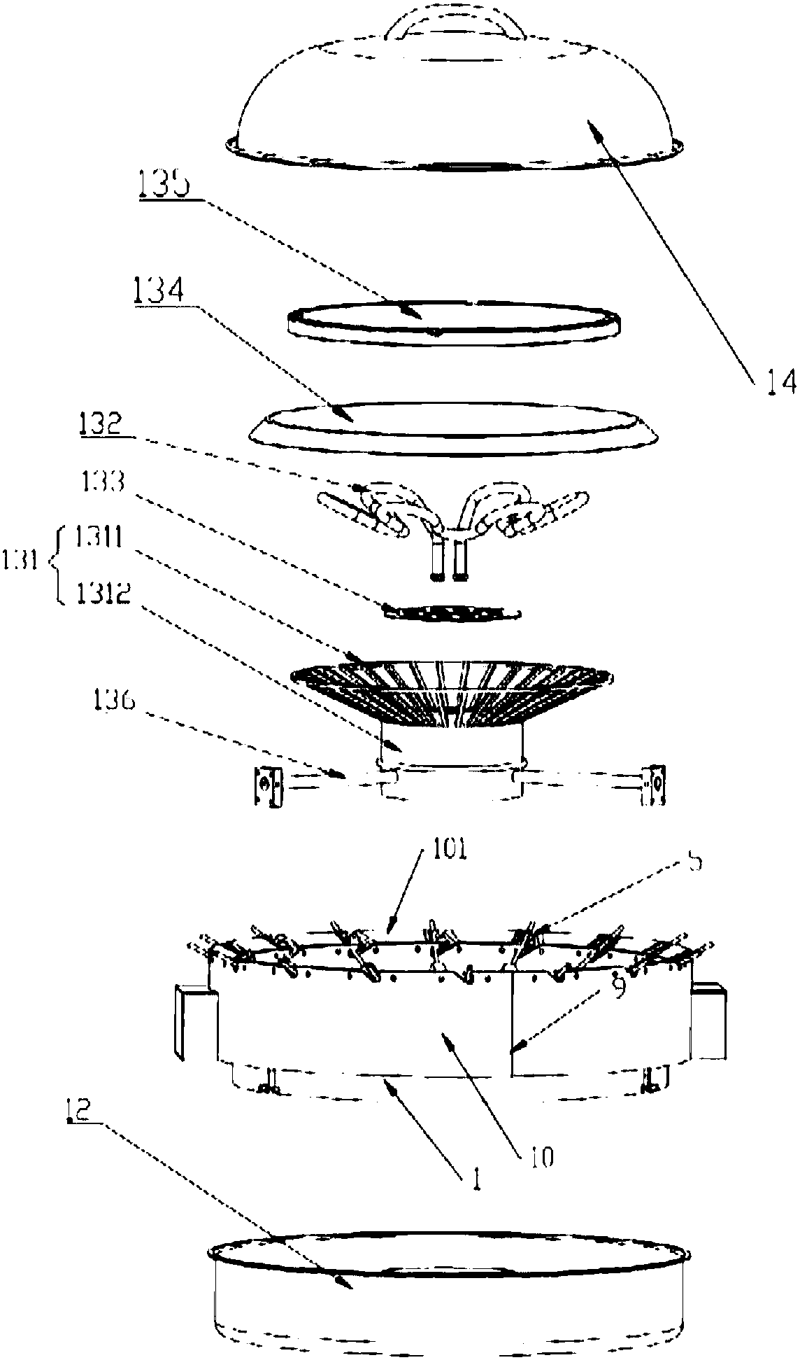
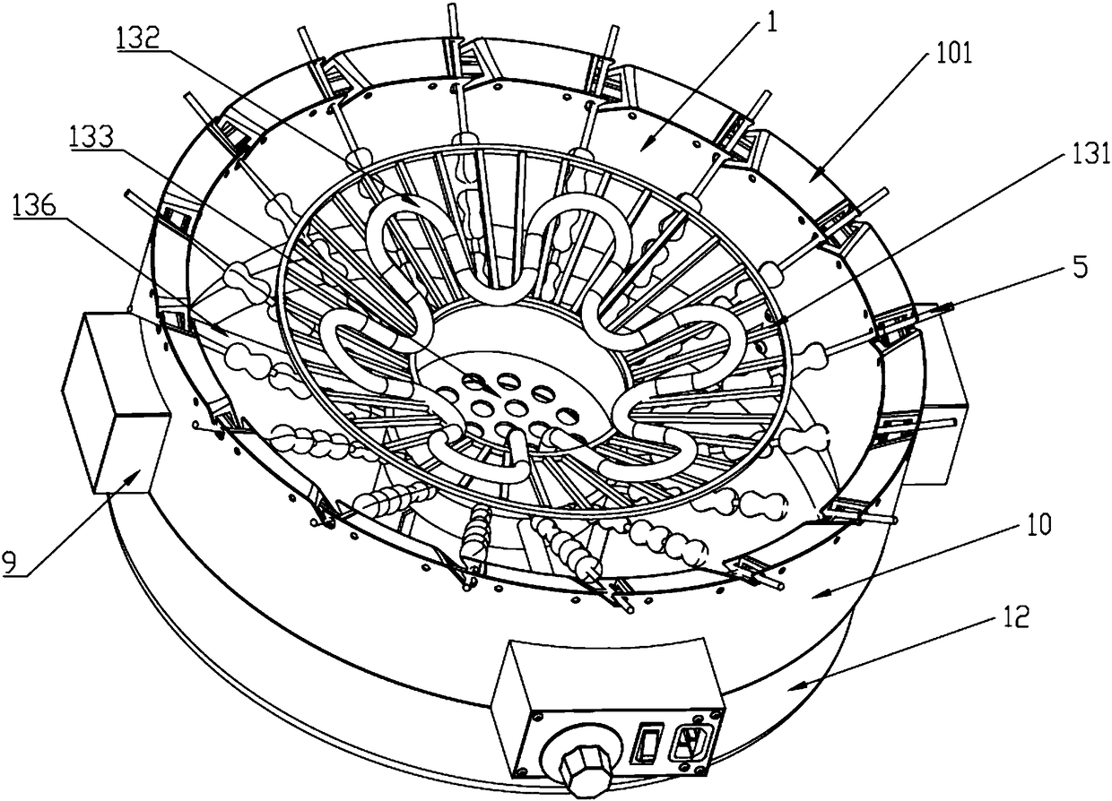
[0069] like figure 1 , figure 2 , Image 6 Shown, a kind of brazier type stone simmers electric barbecue oven, comprises furnace body, furnace core 13, barbecue skewer mechanism and furnace cover 14; Furnace core 13 is fixed in furnace body; Heating plate 132, baking plate 135; the core body 131 includes a connecting portion 1311 and a hollowed-out receiving portion 1312, the simmering plate 133 is fixed in the connecting portion 1311 of the core body, the electric heating plate is fixed on the simmering plate, and the core body 13 The inner wall is set, and the electric heating plate 132 wires extend out of the furnace body through the wire tube 136 to connect with the power supply; the baking pan 135 is installed on the hollow receiving part 1312 of the core body 131; the hollow receiving part makes the projected area of the baking pan 135 on the vertical plane It is larger than the connection part 1311; the skewer mechanism includes a limit groove 4 arranged on the fur...
Embodiment 2
[0072] like figure 1 — Figure 12 As shown, it is different from the above embodiment. In this embodiment, an autorotation mechanism is added. The autorotation mechanism includes a rail 11, a slider 2, and a motor 3; the rail 11 is fixed outside the furnace body 1, and the slider 2 bites on the rail 11 The upper surface of the slider 2 is in friction contact with the baking pin 5; the motor 3 is fixed on the furnace body 1 through the motor bracket 9, and the motor shaft 31 is in friction contact with the lower surface of the slider 2; the motor 3 rotates and the friction pushes the slider 2 along the track 11 Sliding; the sliding block 2 frictionally pushes the roasting needle 5 to self-rotate in the limiting groove 4 .
[0073] The autorotation mechanism in the present invention adopts the mutual friction between the slider 2 and the roasting pin 5, so that the roasting pin 5 can rotate by rubbing under the limit action of the limiting groove 4, and the rotation is stable a...
Embodiment 3
[0075] like figure 1 — Figure 12As shown, different from the above embodiment, in this embodiment, a sliding mechanism is provided on the contact surface between the slider 2 and the track 11, and the slider 2 includes an upper transmission block 21, a lower transmission block 22, and a side transmission connecting the upper and lower transmission blocks. Block 23; the track is bitten between the upper transmission block 21 and the lower transmission block 22, and the first rolling mechanism 6 is respectively set on the contact surfaces of the upper and lower transmission blocks and the track to make the slider slide along the track; the first rolling mechanism 6 It includes a ball accommodation cavity arranged on the upper or lower transmission block, a ball plug 62, a first spring 63, and a ball 61; the ball accommodation cavity has a spherical space, and a ball opening is arranged on one side of the spherical space, and the ball opening The diameter is smaller than the di...
PUM
 Abstract
Description
Claims
Application Information
 - R&D
- Intellectual Property
- Life Sciences
- Materials
- Tech Scout
- Unparalleled Data Quality
- Higher Quality Content
- 60% Fewer Hallucinations
Browse by: Latest US Patents, China's latest patents, Technical Efficacy Thesaurus, Application Domain, Technology Topic, Popular Technical Reports.
© 2025 PatSnap. All rights reserved.Legal|Privacy policy|Modern Slavery Act Transparency Statement|Sitemap|About US| Contact US: help@patsnap.com


