Tooling fixture for rotary welding

A technology of rotary welding and jigs, which is applied in welding equipment, manufacturing tools, auxiliary welding equipment, etc., can solve problems such as poor flexibility, difficulties, and inability to adjust the position of tooling and jigs, and achieve the effect of improving flexibility and simple structure

Active Publication Date: 2019-12-31
佛山市顺德区亿顺五金电器制造有限公司
View PDF4 Cites 1 Cited by
  • Summary
  • Abstract
  • Description
  • Claims
  • Application Information

AI Technical Summary

Problems solved by technology

Taking the cylindrical workpiece as an example, due to its special structure, it needs to be clamped by tooling fixtures to avoid its movement, and because the workpiece is relatively large, it is also difficult to adjust the position of the machining operation. Traditional tooling The jig cannot realize the position adjustment after processing, and the flexibility is poor

Method used


Image

  • Tooling fixture for rotary welding
  • Tooling fixture for rotary welding
  • Tooling fixture for rotary welding

Examples


Embodiment Construction

[0018] In order to make the above objects, features and advantages of the present invention more comprehensible, specific implementations of the present invention will be described in detail below in conjunction with the accompanying drawings.

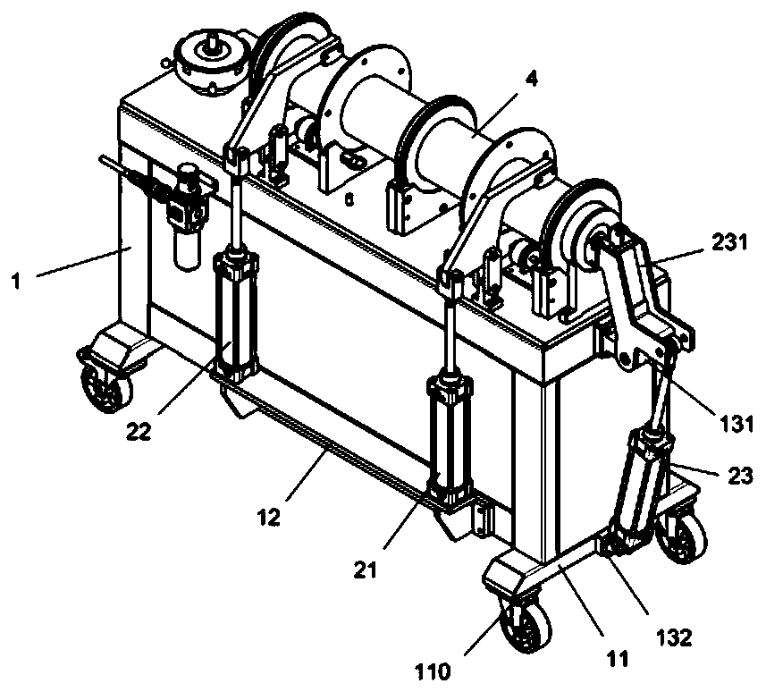
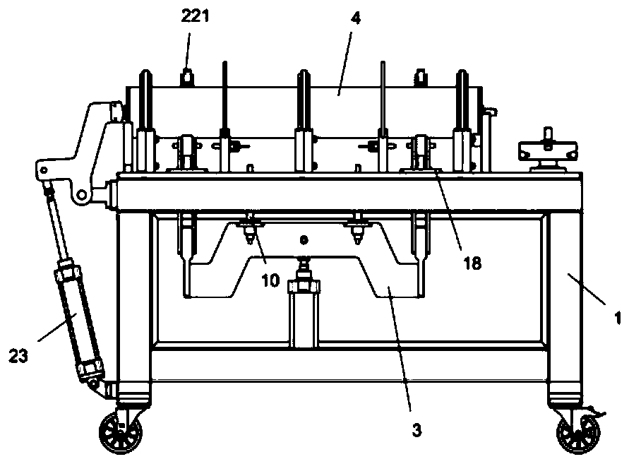
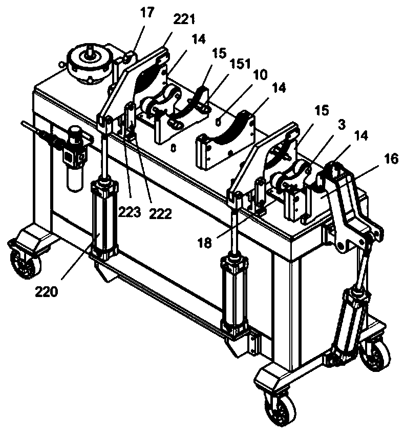
[0019] Such as Figure 1-5 As shown, a tooling fixture for rotary welding includes a frame 1, a workpiece supporting unit, a workpiece pressing unit and a workpiece lifting unit 3, wherein the workpiece supporting unit is fixedly arranged on the top surface of the frame 1, and is to be welded The workpiece 4 is placed on the workpiece supporting unit, and the body of the workpiece 4 to be welded is a cylindrical structure, and a positioning plate 42 is fixed on the middle part and both sides, and a flange plate 41 is fixedly arranged between two adjacent positioning plates 42. A number of flange fixing holes are provided on the blue plate 41, and positioning heads 43 are also provided on both sides of the workpiece 4 to be welded; The...


PUM


Abstract

The invention discloses a tool jig for spin welding. The tool jig comprises a machine frame, a workpiece supporting unit, a workpiece holding unit and a workpiece lifting unit. The workpiece supporting unit is fixedly arranged on the top end surface of the machine frame, a workpiece to be welded is placed on the workpiece supporting unit, the workpiece holding unit is installed on the side of themachine frame, the upper part and side part of the workpiece to be welded are held and fixed, and the workpiece lifting unit is fixedly mounted on the internal bottom end face of the machine frame. The tool jig for the spin welding is simple in structure, support and fixation of a workpiece can be achieved, at the same time, the rotary support of the workpiece can be realized by rollers, the machining position of the workpiece is further adjusted, the needs of welding operation are met, and the flexibility of the welding process is improved.

Description

Technical field: [0001] The invention relates to the technical field of spin welding, in particular to a tooling fixture for spin welding. Background technique: [0002] In the process of industrial production, various non-standard workpieces are often encountered. When processing these non-standard workpieces, it is necessary to support, fix and adjust the position of the non-standard workpieces, which requires the use of tooling fixtures. Taking the cylindrical workpiece as an example, due to its special structure, it needs to be clamped by the tooling fixture to avoid its movement. And because the workpiece is relatively large, it is also difficult to adjust the position of the processing operation. The traditional tooling The jig cannot realize the position adjustment after processing, and the flexibility is poor. Invention content: [0003] The object of the present invention is to provide a tooling fixture for spin welding to address the deficiencies of the prior ar...

Claims


Application Information

Patent Timeline
Patent Type & Authority Patents(China)
IPC IPC(8): B23K37/053
CPCB23K37/053
Inventor 李胜利
Owner 佛山市顺德区亿顺五金电器制造有限公司
Why Eureka
Try Eureka