Grabbing mechanical arm

A technology of a robotic arm and a grasping device, applied in the field of machinery, can solve the problems of inaccurate positioning of grasping workpieces, increase the grasping force of the clamping arm, and reduce the grasping efficiency, so as to solve the inaccurate positioning and increase the grasping force. , the effect of improving convenience

Inactive Publication Date: 2018-09-04
清远市天勤电子科技有限公司
View PDF1 Cites 2 Cited by
  • Summary
  • Abstract
  • Description
  • Claims
  • Application Information

AI Technical Summary

Problems solved by technology

[0004] In view of the deficiencies in the prior art, the object of the present invention is to provide a grasping mechanical arm, which can make the clamping arm shrink inward through the force spring, so as to achieve the effect of increasing the grasping force of the clamping arm, and solve the problem caused by The workpiece is too heavy, which causes the workpiece to slip easily from the clamping arm, which effectively improves the quality of the clamping arm, avoids the axial deviation of the clamping arm, and effectively improves the stability of the mechanical arm structure. It solves the problem of inaccurate positioning when grabbing workpieces, solves the problem that grabbing workpieces is easily affected by distance, effectively improves the convenience of grabbing workpieces, and achieves the effect of grabbing from multiple angles, thereby avoiding repeated movement The base grabs the workpiece, which solves the problem that the grabbing device is easily affected by the different placement of the workpiece and reduces the grabbing efficiency, avoids the phenomenon of displacement of the horizontal telescopic axis, and can achieve the effect of buffering force, which solves the problem of The horizontal telescopic shaft is prone to deformation due to excessive load

Method used


Image

  • Grabbing mechanical arm
  • Grabbing mechanical arm
  • Grabbing mechanical arm

Examples


Embodiment Construction

[0023] The following will clearly and completely describe the technical solutions in the embodiments of the present invention with reference to the accompanying drawings in the embodiments of the present invention. Obviously, the described embodiments are only some, not all, embodiments of the present invention. Based on the embodiments of the present invention, all other embodiments obtained by persons of ordinary skill in the art without making creative efforts belong to the protection scope of the present invention.

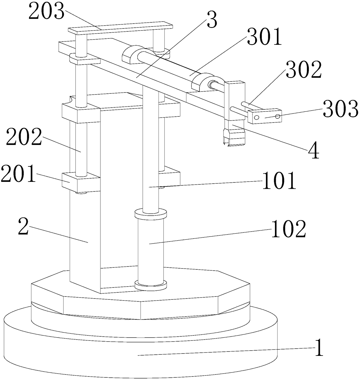
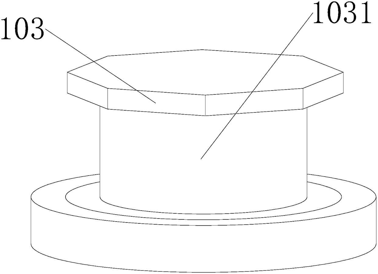
[0024] see Figure 1-4 , the present invention provides a technical solution: a grasping mechanical arm, including a base 1, a support frame 2, a grasping device 4 and a force spring 404, the upper part of the base 1 is closely attached to a rotating tray 103, and the rotating tray 103 can make the support frame 2 rotate in the horizontal direction, thereby achieving the effect of grabbing at multiple angles, thereby avoiding the repeated movement of the base ...


PUM


Abstract

The invention discloses a grabbing mechanical arm, and belongs to the field of machines. According to the technical scheme, the grabbing mechanical arm comprises a base, a supporting frame, a grabbingdevice and a stress application spring; a rotating tray is tightly attached to the upper portion of the base, the supporting frame is fixedly connected to the outer wall of the upper portion of the rotating tray, fixing blocks are fixedly connected to the two sides of the outer wall of the supporting frame, a vertical positioning shaft is in through connection with the middles of the fixing blocks, a hydraulic air cylinder is fixedly connected to the upper portion of the rotating tray, the upper portion of the hydraulic air cylinder is in through connection with a vertical telescopic shaft, the upper end of the vertical telescopic shaft is fixedly connected with a lifting rod, and the side, away from the supporting frame, of the lifting rod is in through connection with two transverse positioning shafts. Through the stress application spring, a clamping arm can shrink inwards, the effect of increasing the grabbing force of the clamping arm is achieved, the problem that due to too heavy workpieces, the workpieces are prone to slipping away from the clamping arm is solved, the grabbing quality of the clamping arm can be effectively improved, axial deviation of the clamping arm can be avoided, and structure stability of the mechanical arm is effectively improved.

Description

technical field [0001] The invention relates to the mechanical field, in particular to a grabbing robot arm. Background technique [0002] The grabbing robot arm is a device for clamping and grabbing workpieces. The clamping teeth fixedly installed on the outer wall of the clamping arm are clamped and clamped with the workpiece, so as to achieve the effect of grabbing and effectively avoid the damage caused by manual grabbing. It is a labor-intensive and time-consuming problem, but the workpiece is easy to slip away from the clamping arm, and the clamping arm is prone to axial deviation, the positioning of the workpiece is not accurate when grasping, and it is impossible to grasp the workpiece from multiple angles, which reduces the grasping efficiency and horizontal expansion Shafts are prone to deformation due to heavy loads. [0003] The Chinese patent with the authorized notification number CN206825411U discloses a grabbing robot arm, including a base, a support rod and...

Claims


Application Information

Patent Timeline
Patent Type & Authority Applications(China)
IPC IPC(8): B25J9/02B25J9/08B25J15/00B25J19/00
CPCB25J9/02B25J9/08B25J15/00B25J19/00
Inventor 张紫婷
Owner 清远市天勤电子科技有限公司
Why Eureka
Try Eureka