Supercharge Your Innovation With Domain-Expert AI Agents!

Timely temperature response open mill roller device

A technology of temperature response and open mill, applied in the field of open mill, can solve the problems of reducing heat exchange efficiency, unfavorable energy consumption, improvement, etc., and achieve the effect of increasing heat exchange rate and improving effective utilization rate

Inactive Publication Date: 2018-09-04
昕中和成都胶业有限公司
View PDF0 Cites 1 Cited by
  • Summary
  • Abstract
  • Description
  • Claims
  • Application Information

AI Technical Summary

Problems solved by technology

However, the existing mill is heated or cooled through the cavity inside the roller. The heat exchange process needs to pass through the thick roller wall, and the heat transfer efficiency is low, which is not conducive to the reduction of energy consumption and the improvement of heat exchange efficiency. promote

Method used


Image

  • Timely temperature response open mill roller device

Examples


Embodiment 1

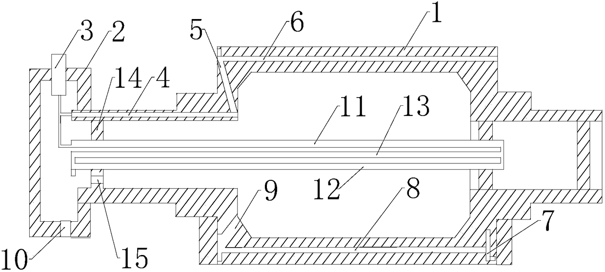
[0021] like figure 1 As shown, a mill roller device with timely temperature response includes a roller body 1 with an inner cavity, the front end of the roller body 1 is connected with a fixed rotary joint 2, and the end of the roller body 1 is connected with a The connection flange, the fixed rotary joint 2 is a cavity structure, the fixed rotary joint 2 is connected with the first flow channel 3 for the working medium to enter, and the outer wall of the front end side of the roller body 1 is opened along the long axis direction and the second flow channel. The second flow channel 4 communicated with the flow channel 3, the outer wall of the front end of the roller shell 1 is provided with the third flow channel 5 communicating with the second flow along the radial direction, and the outer wall of one side of the roller shell 1 is along the length A fourth flow channel 6 communicating with the third flow channel 5 is opened in the axial direction, and a fifth flow channel 7 c...

Embodiment 2

[0024] Similar to Embodiment 1, a secondary cooling device is also provided in the inner cavity of the roller shell 1, and the secondary cooling device includes an inflow channel 11 for the working medium to enter and an outflow channel 12 for the output of the working medium, and the inflow channel 11 is connected with the outflow channel 12 and the inflow channel 11 and the outflow channel 12 are arranged in parallel. 2 cavity structure. The function of installing the secondary cooling device is that the working medium entering from the first flow channel 3 can circulate in the secondary cooling device, and during its circulation, it will exchange heat with the working medium flowing through the outer wall channel of the roller body 1 Heat exchange is performed, thereby preventing heat exchange between the working medium that newly enters the outer wall of the roller body 1 and the heat-exchanged working medium that has entered the cavity of the roller body 1 , thereby impro...


PUM


Abstract

The invention discloses a timely temperature response open mill roller device. The timely temperature response open mill roller device comprises a roller body with an inner cavity. The front end of the roller body is connected with a fixed rotation connector. The interior of the fixed rotation connector is of a cavity structure. The fixed rotation connector is connected with a first runner for working medium inflow. A second runner communicating with the first runner is formed in the outer wall of one side of the front end of the roller body in the long axis direction. A third runner communicating with the second runner is formed in the outer wall of the front end of the roller body in the radial direction. An inner cavity of the roller body communicates with the cavity structure in the fixed rotation connector. A first outflow port for outflow of fluid obtained after cold-heat exchange is formed in the lower portion of the fixed rotation connector. The multiple runners are formed in the outer wall of the roller body, working media can circulate at the position close to the surface of the roller body, on the basis that the distance between a heat exchange medium and the surface ofthe roller body is drawn close, the heat exchange rate is increased, and the effective utilization rate of energy is increased.

Description

technical field [0001] The invention relates to the technical field of mills, in particular to a mill roller device with timely temperature response. Background technique [0002] The main working parts of the open mill are two hollow rollers or drilled rollers that rotate inward in different directions. The one installed on the operator's side is called the front roller, which can be moved back and forth horizontally by manual or electric action to adjust the roller distance. Adapt to the operation requirements; the rear roller is fixed and cannot move back and forth. The size of the two rollers is generally the same, and they rotate relative to each other at different speeds. The raw rubber or rubber material is drawn into the gap between the two rollers with the rotation of the rollers, and is subjected to strong shearing to achieve the purpose of mastication or mixing. Mills are also used in sectors such as plastics processing. [0003] In the rubber mixing process of ...

Claims


Application Information

Patent Timeline
IPC IPC(8): B29B7/62B29B7/82
CPCB29B7/625
Inventor 彭亮郭克富吴佳伟
Owner 昕中和成都胶业有限公司
Features
  • R&D
  • Intellectual Property
  • Life Sciences
  • Materials
  • Tech Scout
  • Unparalleled Data Quality
  • Higher Quality Content
  • 60% Fewer Hallucinations
Learn More