Automatic positioning and charging device and method for unmanned aerial vehicle

An automatic positioning and charging device technology, applied in the field of drones, can solve the problems of large electrode area, high cost, lack of drone positioning devices, etc., and achieve the effect of simple overall structure, good positioning effect and easy maintenance

Pending Publication Date: 2018-09-04
深圳草莓创新技术有限公司
View PDF10 Cites 21 Cited by
  • Summary
  • Abstract
  • Description
  • Claims
  • Application Information

AI Technical Summary

Problems solved by technology

[0002] The UAV airport can provide a docking place for the UAV, automatically charge the UAV, or provide the function of automatically replacing the battery; the existing UAV airports mostly use the method of setting contacts between the UAV and the bottom plate for charging , there is a lack of a device for positioning the UAV, the electrode area that needs to be set on the bottom plate is large, the contacts are easily damaged, the cost is high, the contact is poor, and it is not convenient to automatically replace the battery of the UAV

Method used


Image

  • Automatic positioning and charging device and method for unmanned aerial vehicle
  • Automatic positioning and charging device and method for unmanned aerial vehicle
  • Automatic positioning and charging device and method for unmanned aerial vehicle

Examples


Embodiment Construction

[0022] In order to make the purpose, technical solutions and advantages of the embodiments of the present invention clearer, a clear and complete description will be made below in conjunction with the technical solutions in the embodiments of the present invention. Obviously, the described embodiments are part of the embodiments of the present invention, and Not all examples. Based on the embodiments of the present invention, all other embodiments obtained by persons of ordinary skill in the art without making creative efforts belong to the protection scope of the present invention.

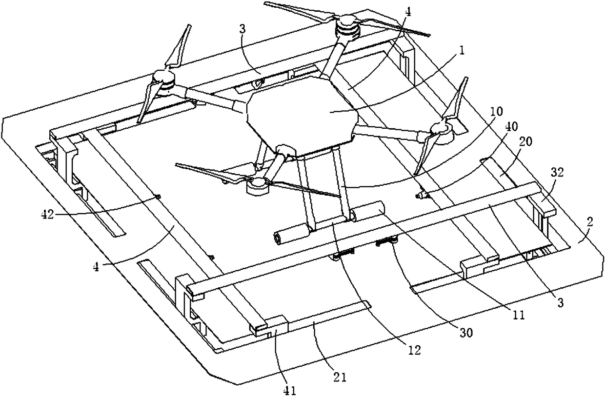
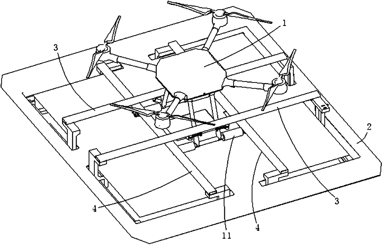
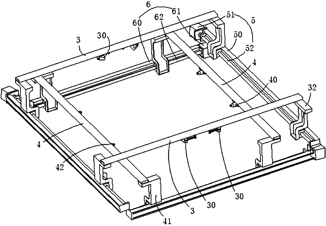
[0023] The UAV automatic positioning charging device of the preferred embodiment of the present invention is as follows: figure 1 shown, see also figure 2 , image 3 and Figure 4 , including a bottom plate 2 for the UAV 1 to land, two parallel first push rods 3 respectively located on both sides of the UAV 1, a first drive mechanism 5 for driving the two first push rods 3 to approach or sepa...


PUM


Abstract

The invention relates to an automatic positioning and charging device for an unmanned aerial vehicle. The device comprises a baseplate for the unmanned aerial vehicle to land on, two parallel first push rods arranged at the two sides of the unmanned aerial vehicle respectively, a first driving mechanism for driving the two first push rods to approach or be separated from each other, two parallel second push rods arranged at the two sides of the unmanned aerial vehicle respectively and a second driving mechanism for driving the two second push rods to conduct approach or separation motion; thefirst push rods are vertical to the second push rods; limit parts matched with supporting feet of the unmanned aerial vehicle and reset springs for resetting after the limit parts rotate are rotatablyconnected to the first push rods; horizontal charging ports are formed in the unmanned aerial vehicle; charging connectors corresponding to the charging ports are formed in the second push rods. Theautomatic positioning and charging device is good in positioning effect, butt joint of the charging connectors and the charging ports are completed while positioning is completed, automatic separationis also facilitated after charging is completed at the same time, and a condition is provided for automatic replacement of a battery of the unmanned aerial vehicle; the device is simple in overall structure, complete in function, low in cost and easy to maintain.

Description

technical field [0001] The invention relates to the technical field of unmanned aerial vehicles, and more specifically, relates to an automatic positioning and charging device for an unmanned aerial vehicle and a method thereof. Background technique [0002] The UAV airport can provide a docking place for the UAV, automatically charge the UAV, or provide the function of automatically replacing the battery; the existing UAV airports mostly use the method of setting contacts between the UAV and the bottom plate for charging , the lack of a device for positioning the UAV, the electrode area that needs to be set on the bottom plate is large, the contacts are easily damaged, the cost is high, the contact is poor, and it is inconvenient to automatically replace the battery of the UAV. Contents of the invention [0003] The technical problem to be solved by the present invention is to provide a UAV automatic positioning charging device for the above-mentioned defects of the prior...

Claims


Application Information

Patent Timeline
Patent Type & Authority Applications(China)
IPC IPC(8): B64F1/00B64F1/12B60L11/18
CPCB64F1/00B64F1/125B60L53/16B60L53/36B60L2200/10Y02T10/70Y02T90/12Y02T10/7072Y02T90/14
Inventor 杨陆见侯小野施永鑫张凤阁
Owner 深圳草莓创新技术有限公司
Why Eureka
Try Eureka