
Feeding structure for providing stock bin of rotary vibrating screen

A technology of rotary vibrating screen and silo, which is applied in the direction of conveying bulk materials, conveyors, transportation and packaging, etc. It can solve the problems of waste, poor fixation and connection, and easy shaking of the suction pipe, so as to achieve easy connection and convenience The effect of dismantling and cleaning

Pending Publication Date: 2018-09-04
XINXIANG DONGZHEN MACHINERY
View PDF0 Cites 0 Cited by
  • Summary
  • Abstract
  • Description
  • Claims
  • Application Information

AI Technical Summary

Problems solved by technology

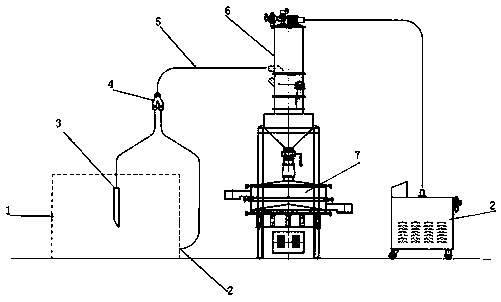
[0002] The rotary vibrating screen is a high-precision fine powder screening machine, which is widely used in industry, ceramics, papermaking, metallurgy, and pharmaceutical industries. The feed port on the rotary vibrating screen is generally the same as that of the vacuum feeder. The outlet of the vacuum feeder is docked with the feed port on one side of the vacuum feeder and the silo. The head of the vacuum feeder is provided with a connection port with the vortex air pump. If the silo is a square silo, there are two Suction ports, one is located at the bottom of the silo, and the other is located at the top of the silo. The two suction ports correspond to two suction pipes to feed the vacuum feeder. The disadvantage is that the two suction pipes are side by side. It is not easy to fix and connect, and the suction pipe is easy to shake when feeding, so it needs to be supported by a special person to keep it stable. This kind of feeding structure is wasteful and troublesome

Method used


Image

  • Feeding structure for providing stock bin of rotary vibrating screen
  • Feeding structure for providing stock bin of rotary vibrating screen

Examples


Embodiment Construction

[0008] Embodiments of the present invention are described in detail below, examples of which are shown in the drawings, wherein the same or similar reference numerals designate the same or similar elements or elements having the same or similar functions throughout. The embodiments described below by referring to the figures are exemplary and are intended to explain the present invention and should not be construed as limiting the present invention.

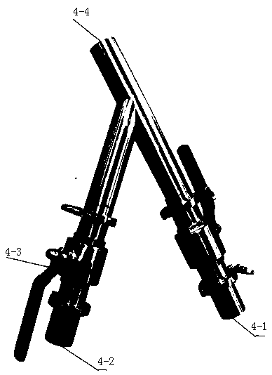
[0009] Specific examples figure 1 with figure 2 As shown, the silo structure of the technical solution includes a silo 1, a bottom suction port 2, a material suction port 3, and a tee joint 4. The top of the silo 1 is provided with a material suction port 3, and the bottom of the silo is a There is a bottom suction port 2 on the side, each suction port is connected with a suction pipe, the suction pipe is higher than the silo and enters the three-way joint, and the outlet of the three-way joint is connected with a delivery pipe...


PUM


Abstract

The invention discloses a stock bin structure provided with a feeding port of a rotary vibrating screen. According to the technical scheme, the stock bin structure comprises a stock bin body, materialsuction ports, a bottom suction port and a three-way joint, wherein the material suction ports are formed in the upper part of the stock bin, the bottom material suction port is formed in one side ofthe bottom of the stock bin, each material suction port is connected with a material suction pipe, the material suction pipes are higher than the stock bin and connected with a three-way joint, and an outlet of the three-way joint is connected with a conveying pipe and the conveying pipe is connected with the feeding port of a vacuum feeding machine; and a vortex air pump is connected with a vacuum tube, and the vacuum tube is connected with a vacuum generator on the vacuum feeding machine, and a discharging port in the vacuum feeding machine is connected with the feeding hole in the rotary vibrating screen. According to the technical scheme, the feeding structure for providing a stock bin of a rotary vibrating screen has the beneficial effects that one feeding pipe is reduced, a person does not need to hold the material suction pipes during feeding, connection is facilitated, disassembly and clearing are carried out conveniently, shaking is not existed during the feeding, fixing is easy and the like.

Description

technical field [0001] The invention relates to a material feeding structure of a silo, which is especially suitable for use when providing material feeding with a rotary vibrating screen. Background technique [0002] The rotary vibrating screen is a high-precision fine powder screening machine, which is widely used in industry, ceramics, papermaking, metallurgy, and pharmaceutical industries. The feed port on the rotary vibrating screen is generally the same as that of the vacuum feeder. The outlet of the vacuum feeder is docked with the feed port on one side of the vacuum feeder and the silo. The head of the vacuum feeder is provided with a connection port with the vortex air pump. If the silo is a square silo, there are two Suction ports, one is located at the bottom of the silo, and the other is located at the top of the silo. The two suction ports correspond to two suction pipes to feed the vacuum feeder. The disadvantage is that the two suction pipes are side by side....

Claims


Application Information

Patent Timeline
IPC IPC(8): B65G53/52B65G53/24
CPCB65G53/24B65G53/52
Inventor 韩磊崔立达杨福音吕超
Owner XINXIANG DONGZHEN MACHINERY
Learn More