City utility tunnel

An integrated pipe gallery and city technology, applied in the direction of pipe supports, pipes/pipe joints/pipes, water conservancy projects, etc., can solve the problems of inconvenient fixed support of pipes, inconvenient management, backflow of rainwater from ventilation pipes, etc., to improve convenience and stability, avoid damage to structural strength, and ensure the effect of installation stability

Active Publication Date: 2018-09-04
湖南飞山奇建筑科技有限公司
View PDF5 Cites 4 Cited by
  • Summary
  • Abstract
  • Description
  • Claims
  • Application Information

AI Technical Summary

Problems solved by technology

[0003] Most of the existing integrated pipe galleries are made of pipe gallery units suitable for concrete pouring, and there are still some shortcomings in actual use. For example, in order to ensure the stability of the pipeline, it is generally necessary to install pipe brackets inside the integrated pipe gallery , but the existing structural form is to splice the pipe gallery first, and then rotate and install it again. Not only is the operation complicated, it is inconvenient to manage, but it is also easy to damage the structural strength of the pipe gallery unit, the use effect is not ideal, and the safety is poor , it is not convenient to fix and support the pipes, and because the comprehensive pipe gallery is located under the ground, it needs to ventilate the interior, and the existing structure does not have ventilation pipes for ventilation, which not only has poor heat dissipation, but also easily causes internal air pollution. Turbidity affects the health of maintenance personnel, and the separate ventilation pipes are likely to cause rainwater to flow back, affecting internal safety and stability, and the use effect is not ideal

Method used


Image

  • City utility tunnel
  • City utility tunnel
  • City utility tunnel

Examples


Embodiment Construction

[0022] The following will clearly and completely describe the technical solutions in the embodiments of the present invention with reference to the accompanying drawings in the embodiments of the present invention. Obviously, the described embodiments are only some, not all, embodiments of the present invention. Based on the embodiments of the present invention, all other embodiments obtained by persons of ordinary skill in the art without making creative efforts belong to the protection scope of the present invention.

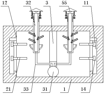
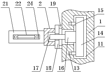
[0023] see Figure 1-6 , the present invention provides a technical solution: a comprehensive urban pipe gallery, including a pipe gallery unit body 1, T-shaped installation grooves 11 are provided on both sides of the interior of the pipe gallery unit body 1, and the upper surface of the T-shaped installation groove 11 is provided with There is a notch slot 12 with a relatively large opening, which is convenient for putting the T-shaped mounting block 14 insi...


PUM


Abstract

The invention discloses a city utility tunnel. The city utility tunnel comprises tunnel unit bodies. T-shaped installation grooves are formed in both the two sides of the interior of each tunnel unitbody. A placement opening groove is formed in the upper surface of each T-shaped installation groove. A positioning hole is formed in the front end of the inner side surface of each T-shaped installation groove. A T-shaped installation block is in sliding connection with the inner side surface of each T-shaped installation groove. Both the two sides of the surface of the front end of each T-shapedinstallation block are connected with the inner side surface of the corresponding positioning hole through positioning rods in a sliding manner. The surface of the front end of each T-shaped installation block is connected to an opening in the front end of the interior of the corresponding T-shaped installation groove through a connecting block in a sliding manner. An installation screw is arranged on the surface of the front end of each connecting block. An installation nut is in thread connection with the outer surface of each installation screw. The rear side surface of each installation nut is connected to the front end of the inner side surface of each tunnel unit body through a top block in a sliding manner. With the city utility tunnel, convenience and stability of usage can be greatly improved, and safety is guaranteed.

Description

technical field [0001] The invention relates to the technical field of urban construction, in particular to an urban comprehensive pipe gallery. Background technique [0002] The comprehensive pipe corridor is the comprehensive corridor of underground urban pipelines, that is, to build a tunnel space underground in the city, integrating various engineering pipelines such as power, communication, gas, heating, water supply and drainage, etc., with special inspection ports and detection systems. Implement unified planning, unified design and management, due to urban management and operation. [0003] Most of the existing integrated pipe galleries are made of pipe gallery units suitable for concrete pouring, and there are still some shortcomings in actual use. For example, in order to ensure the stability of the pipeline, it is generally necessary to install pipe brackets inside the integrated pipe gallery , but the existing structural form is to splice the pipe gallery first,...

Claims


Application Information

Patent Timeline
Patent Type & Authority Applications(China)
IPC IPC(8): E02D29/045F16L3/10
CPCE02D29/10F16L3/10
Inventor 蒋志威严伍玖李超
Owner 湖南飞山奇建筑科技有限公司
Why Eureka
Try Eureka