
Method and device for detecting karst geology through elastic wave imaging chromatography

A detection device and imaging layer technology, which is applied in the field of engineering survey, can solve the problems affecting the accuracy, the collision of the inner wall of the borehole, and the service life of the broken rope, so as to ensure the stability of the installation, facilitate the quick disassembly and assembly, and ensure the safety. Effect

Inactive Publication Date: 2021-01-29
高军
View PDF0 Cites 4 Cited by
  • Summary
  • Abstract
  • Description
  • Claims
  • Application Information

AI Technical Summary

Problems solved by technology

[0003] However, when the existing detection devices are used for karst detection in deep boreholes, the detection equipment is generally suspended in the borehole by a suspension rope for detection. In order to prevent the detection equipment from being scratched in the borehole, its volume is generally smaller than that of the drill The diameter of the hole, thus causing the shaking of the detection equipment when it descends in the borehole, the shaking will collide with the inner wall of the borehole, which is likely to cause damage to the equipment and affect the accuracy of detection; and the sling of the detection equipment is suspended It is easy to rub against the inner wall of the borehole, and the intense friction will easily cause the sling to break and reduce its service life, and even the sling may be cut by sharp objects on the inner wall of the borehole, causing the detection equipment to fall and be damaged, resulting in losses

Method used


Image

  • Method and device for detecting karst geology through elastic wave imaging chromatography
  • Method and device for detecting karst geology through elastic wave imaging chromatography
  • Method and device for detecting karst geology through elastic wave imaging chromatography

Examples


Embodiment Construction

[0064] The following will clearly and completely describe the technical solutions in the embodiments of the present invention with reference to the accompanying drawings in the embodiments of the present invention. Obviously, the described embodiments are only some, not all, embodiments of the present invention. Based on the embodiments of the present invention, all other embodiments obtained by persons of ordinary skill in the art without making creative efforts belong to the protection scope of the present invention.

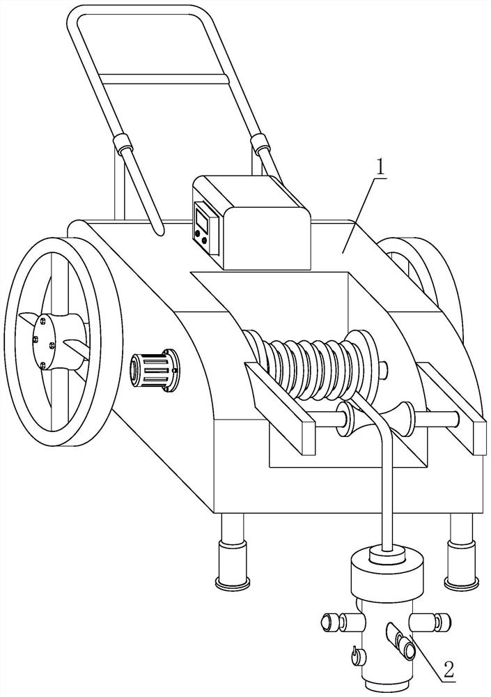
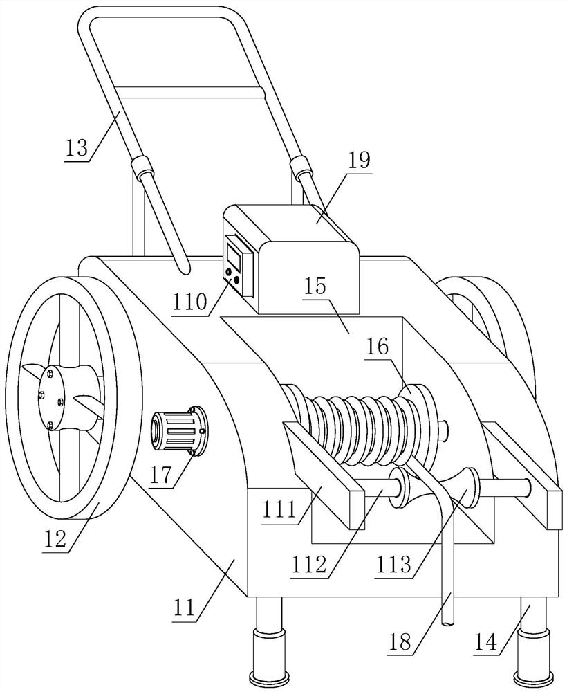
[0065] In order to better demonstrate the elastic wave imaging tomography detection method for karst geology, this embodiment now proposes another elastic wave imaging tomography detection karst geological device:

[0066] see Figure 1-2 , a device for detecting karst geology by elastic wave imaging tomography, comprising a fixing device 1 and a detecting device 2, the detecting device 2 is installed on the fixing device 1, and the fixing device 1 includes a ...


PUM


Abstract

The invention discloses a method for detecting karst geology through elastic wave imaging chromatography, and also discloses a device for detecting karst geology through elastic wave imaging chromatography. The device comprises a fixing device and a detection device, the detection device is installed on the fixing device, and balancing mechanisms are arranged on the side wall of a CT detector in across symmetry manner; an end socket is arranged on the side wall of the CT detector through cooperation of a fixed cylinder, a buffer spring, a piston disc and a movable push rod, a cavity is formedin the end socket to install a ball, the ball extends to the outside of the end socket through a through hole in the side wall of the end socket, and when the CT detector enters a drill hole, the endsocket is pushed to compress the buffer spring through the movable push rod; after the CT detector completely enters the drill hole, the ball is tightly attached to the inner wall of the drill hole under the action of the relaxation force of the buffer spring, when the CT detector descends in the drill hole, and the ball rolls on the inner wall of the drill hole, so the stability of the CT detector during descending is guaranteed, and practicability and convenience are achieved.

Description

technical field [0001] The invention relates to the technical field of engineering survey, in particular to a method and device for elastic wave imaging tomography detection of karst geology. Background technique [0002] In recent years, my country's engineering construction is developing rapidly, and more and more tunnels are being built in unfavorable geological areas, especially in karst-developed areas, where the top surface of bedrock, karst caves, and eroded cracks develop very complex forms. The current conventional engineering geological drilling is difficult to reflect the distribution and shape of underground unfavorable geological bodies due to the limited number of exploration drilling holes and the "one-hole view". The elastic wave CT method has high efficiency, simple operation, accuracy and effectiveness, and overcomes the shortcomings of conventional engineering drilling. [0003] However, when the existing detection devices are used for karst detection in ...

Claims


Application Information

Patent Timeline
Patent Type & Authority Applications(China)
IPC IPC(8): G01V1/00
CPCG01V1/00
Inventor 高军陈敏王岭汤宇刘德安陈红胡恒良薛明智陈志明黄正凯乔保卫张松李行利游国平张晓晓林晓谭发刚
Owner 高军
Learn More