[0037]The present invention will be described in further detail below in conjunction with the accompanying drawings.
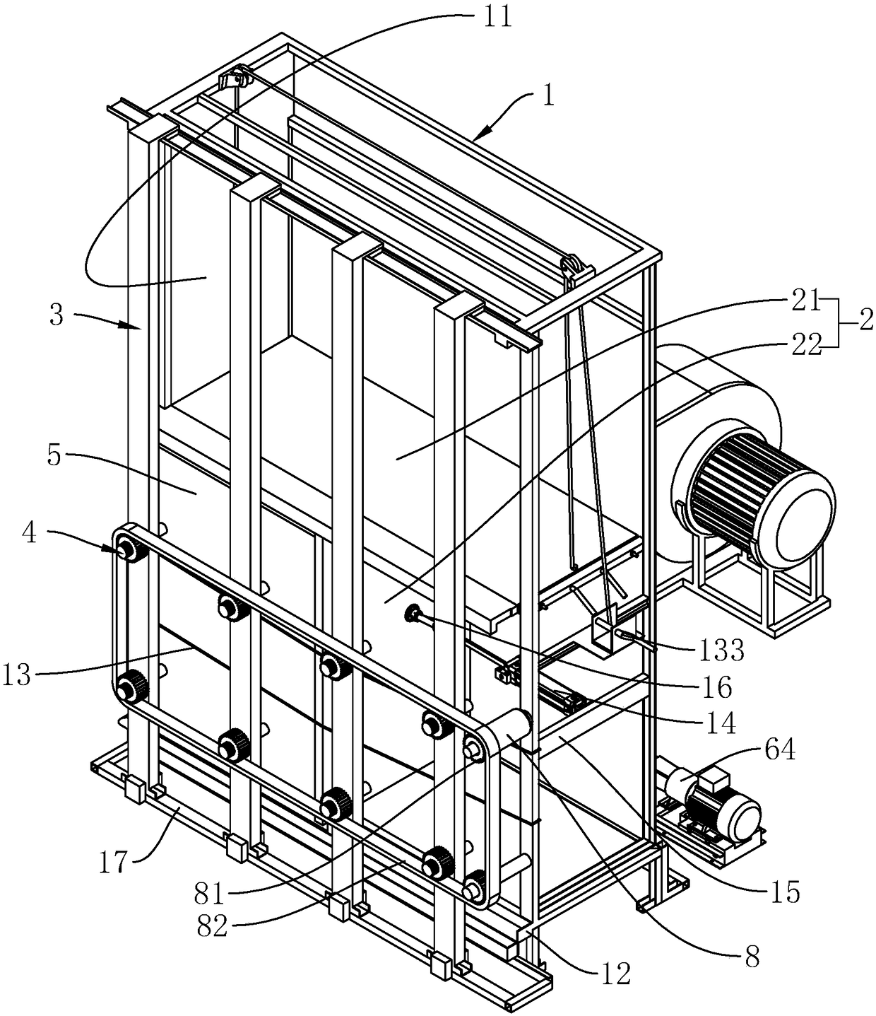
[0038] see figure 1 , a door and window physical performance testing equipment, including a box 1, a partition plate group 2 and a plurality of locking rods 3. The box body 1 is provided with an installation chamber 11 opening toward the locking rod 3 . The partition board set 2 is slidably connected inside the installation cavity 11 , and includes a first partition board 21 and a second partition board 22 that are perpendicular to each other and abut against the box body 1 . The partition plate group 2 separates the box body 1 into a cavity having the same shape and size as the object to be inspected 5 . The locking rod 3 compresses the object 5 to be inspected and the cavity separated from the box body 1 by the partition plate group 2 through the fastener 4 to form a detection cavity for detecting the physical properties of the object to be inspected 5 . In this embodiment, the object 5 to be inspected is selected as a window.
[0039] see figure 2 and image 3 , the box body 1 is connected with a water circulation system for testing the watertightness of the test piece 5 and a wind energy system for testing the airtightness and wind pressure resistance. The water circulation system includes a number of nozzles 61 fixed in the detection chamber, a water tank 63 connected to the bottom of the detection chamber through a water filter hole 62, a circulating water pump 64 connected to the bottom of the water tank 63, and a connecting pipe 65 connecting the circulating water pump 64 and the nozzles 61 . The water in the water tank 63 returns to the water tank 63 through the water filter hole 62 after being sprayed out from the spray nozzle 61 by the circulating water pump 64 to realize water circulation.
[0040] see figure 2 and image 3 The wind energy system includes an air outlet 71 opened on the box body 1 and communicated with the detection chamber, a fan 73 connected to the air outlet 71 through an air outlet pipe 72, and an air inlet pipe 74 connected to the air inlet 71 of the fan 73 . The fan 73 is a centrifugal fan 73, which pumps air from the external environment and transports it to the detection chamber to increase the air pressure in the detection chamber.
[0041] see figure 1 , image 3 and Figure 4 The box body 1 is located below the opening position and is connected with a positioning frame 12, and the box body 1 is located above the positioning frame 12 and bound with several elastic ropes 13 arranged in parallel with the positioning frame 12. The positioning frame 12 is provided with a positioning groove 121 for inserting and abutting the object to be inspected 5 . The positioning frame 12 is located at the bottom of the positioning groove 121 and is provided with an exhaust pipe 75 , and the exhaust pipe 75 communicates with the positioning groove 121 through a plurality of through holes 122 provided at the bottom of the positioning groove 121 . The side of the suction pipe 75 connected to the air inlet pipe 74 creates a negative pressure on the surface of the positioning groove 121 .
[0042] see image 3 and Figure 5 , the first partition plate 21 is longitudinally slidably connected in the installation cavity 11 , and the upper end of the box body 1 located in the installation cavity 11 is connected with two fixed pulleys 131 . Two ends of the first partition plate 21 are respectively connected with connecting ropes 132 wound on the fixed pulley 131 . Winding or unwinding is realized by rotating the shaft 133, so as to achieve the purpose of controlling the lifting of the first partition plate 21 of the motor.
[0043] see figure 1 , image 3 and Figure 5 , the second partition plate 22 is perpendicular to the first partition plate 21 and laterally slidably connected between the first partition plate 21 and the bottom of the installation cavity 11 . One end of the box body 1 located at the opposite detection chamber of the second partition plate 22 is provided with a mounting bracket 15 and a locking cylinder 14 fixed on the mounting bracket 15, and the end of the locking cylinder 14 is hinged with The vacuum chuck 16 on the top, the locking cylinder 14 can press the second partition plate 22 and the object 5 to be inspected.
[0044] see figure 1 , image 3 and Figure 5 One end of the first partition plate 21 facing the part 5 to be inspected is connected with a first clamping plate 211, and the first partition plate 21 and the first clipping plate 211 form a first separation groove for the end of the part 5 to be inspected to be embedded. 212. The second dividing plate 22 is connected with a second clamping plate 221 at its end facing the object to be inspected 5, and the second separating plate 22 and the second clamping plate 221 form a first hole for inserting one side of the object to be inspected 5. Two separation grooves 223 . A joint of the second partition plate 22 and the second clamping plate 221 defines a clamping groove 222 for inserting the first clamping plate 211 .
[0045] see figure 1 , Image 6 and Figure 7 The box body 1 is located in front of the positioning frame 12 and is also connected with a slide rail 17 for installing the locking rod 3 . The locking rod 3 includes a sliding rod 31 and a positioning column 32 equidistantly fixed on the sliding rod 31 . The positioning post 32 is located between the two elastic cords 13 and protrudes away from the installation cavity 11 . The sliding rod 31 is provided with a sliding slot 311 for fitting the sliding rail 17 . The axis of the positioning post 32 is provided with a positioning hole 321 passing through the positioning post 32 and the sliding rod 31 , and the inner wall of the positioning hole 321 is provided with a raised positioning key 322 .
[0046] see figure 1 , Image 6 and Figure 7 , the end of the positioning column 32 is connected with the positioning gear 33 through the limiting ring 323 . The limiting ring 323 is annular with an outer diameter greater than that of the positioning post 32 and an inner diameter consistent with the positioning hole 321 . The positioning gear 33 includes a first connecting portion 331 snapped on the limiting ring 323 and a second connecting portion 332 integrally formed with the first connecting portion 331 . The first connecting portion 331 includes a limiting ring groove 3311 for engaging the limiting ring 323 and a plurality of positioning pieces 334 for limiting the limiting ring 323 to escape from the limiting ring groove 3311 . The limiting ring groove 3311 is an L-shaped ring groove. A plurality of engagement holes 3312 are equally spaced circumferentially on the side wall of the positioning post 32 at the opening of the limiting ring groove 3311 . The positioning piece 334 is interferingly snapped into the clamping hole 3312, and a ball 335 is embedded between the positioning piece 334 and the second connecting portion 332, and the ball 335 can only rotate in situ through the ball groove opened on the positioning piece 334 . The second connecting portion 332 defines a threaded hole 3321 coaxial with the limiting ring groove 3311 along its axis. The diameter of the threaded hole 3321 is located between the limiting ring groove 3311 and the positioning hole 321 .
[0047] see figure 1 , Image 6 and Figure 7 , the fastener 4 includes a positioning rod 41 connected to the positioning post 32 and a fastening portion 42 disposed on the end of the positioning rod 41 facing the box body 1 . The positioning rod 41 includes a smooth rod 411 connected to the positioning hole 321 and a threaded rod 412 engaged with the threaded hole 3321. The threaded rod 412 and the smooth rod 411 are integrally formed in a stepped shape. The smooth rod 411 is provided with a positioning key groove 4111 for embedding the positioning key 322 to limit the axial rotation of the positioning rod 41 . The limiting ring 323 surrounds the second connecting portion 332 to form an abutting groove for the end of the threaded rod 412 to abut against. The fastening part 42 includes a rubber sleeve 421 sleeved on the positioning rod 41 and a plurality of gaskets 422 arranged between the rubber sleeve 421 and the smooth rod 411 .
[0048] see figure 1 Also be provided with driving motor 8 on the casing 1, be provided with driving gear 81 on the motor shaft of driving motor 8, be connected by crawler belt 82 that is sleeved on it between driving gear 81 and positioning gear 33 meshing connection. When the driving motor 8 rotates, it can drive the positioning gear 33 to rotate synchronously with the driving gear 81 .
[0049] When the door and window physical performance testing equipment needs to detect the object 5 to be inspected, the object 5 to be inspected is first placed in the positioning groove 121, so that the edge of the object to be inspected 5 is in contact with the edge of the box body 1, and the elastic rope 13 Pressing on the surface of the object to be inspected 5 further positions the object to be inspected 5 and the box body 1 . Subsequently, according to the height of the surface of the object 5 to be inspected, a spacer 422 is inserted into the rubber sleeve 421 to compensate for the height difference, and then the rubber sleeve 421 is connected to the positioning rod 41 . Then adjust the rotating shaft 133, so that the first partition plate 21 slides toward the direction of the object to be inspected 5, so that the object to be inspected 5 is clamped in the first separation groove 212; the second partition plate 22 with a suitable size is selected, and the It is adsorbed on the vacuum chuck 16, and then the locking cylinder 14 is adjusted so that the second partition plate 22 slides toward the direction of the object to be inspected 5, and the object to be inspected 5 is embedded in the second separation groove 223, so that the first partition plate The partition 21 and the second partition 22 press the object 5 to be inspected. At this time, start the driving motor 8 again, so that the driving gear 81 drives the positioning gear 33 to rotate, so that the positioning rod 41 can be synchronously stretched out to the direction of the object to be inspected 5, so that the fastening part 42 is pressed on the surface of the object to be inspected 5, and The object to be inspected 5 , the first partition plate 21 , the second partition plate 22 and the clamping plate are compressed synchronously to obtain a sealed detection chamber. Afterwards, the watertightness, wind pressure resistance or airtightness performance test of the object 5 to be inspected can be carried out through the water circulation system, the wind energy system and the sensor elements located in the detection chamber according to the requirements.
[0050] This specific embodiment is only an explanation of the present invention, and it is not a limitation of the present invention. Those skilled in the art can make modifications to this embodiment without creative contribution as required after reading this specification, but as long as they are within the rights of the present invention All claims are protected by patent law.