Structured light projection module group and depth camera
A structured light projection and structured light technology, applied in optics, optical components, optical devices, etc., can solve the problem of uniform density distribution of projection patterns of difficult structured light projection modules, achieve high irrelevance, improve density distribution, Evenly distributed effect
Active Publication Date: 2018-09-04
SHENZHEN ORBBEC
11 Cites 11 Cited by
AI-Extracted Technical Summary
Problems solved by technology
[0005] However, in the current scheme, it is difficult to achieve better unity in key indicators such as the power consumption...
View moreMethod used
As can be seen from Fig. 4 (c), the randomness of the speckle distribution at the junction of adjacent blocks can be improved by the arrangement form of mutual coupling between the non-linear contours, but the unfavorable factor is at the edge of the structured light speckle pattern There will also be a non-linear undulating outline at , because the field of view of the acquisition module is often a square (here is still analyzed in an ideal situation, ignoring image distortion), so the effective area 406 of the structured light spot pattern is smaller than all the spot blocks 405 The overall structured light spot pattern 404 is composed.
In order to make the density of the speckle distribution in the structured light speckle pattern relatively uniform and satisfy the irrelevance, on the one hand by designing the arrangement of the sub-light source 202 so that the speckle arrangement inside the speckle block 206 satisfies the irrelevance, on the other hand by The DOE 204 is designed so that each speckle block 206 is arranged in a tiled manner to ensure that all speckle blocks can cover the entire projection area.
In the embodiment shown in Fig. 12, each speckle block in the substructure light speckle pattern is formed by being adjacent to each other, Fig. 13 then provides the embodiment of another kind of overlap scheme, in this embodiment, A certain gap is set between the speckle blocks in the sub-structured light speckle pattern, so as to increase the projected area. Figure 13(a) shows the first structured light spot pattern 1301 composed of speckle blocks with 9 different diffraction orders (corresponding to the horizontal and vertical coordinates in the figure), and Figure 13(b) is shown by The second structured light spot pattern 1302 composed of 9 spot blocks, Fig. 13(c) is a structured light spot pattern formed by interlacing the first and second structured light spot patterns. It can be seen from the figure that the first and second structured light spot patterns are formed by a plurality of spot blocks arranged with a certain gap.
In the embodiment shown in Fig. 4 and Fig. 5, Fig. 4 sets the sub-light source arrangement pattern to the non-linear form of the edge, and Fig. 5 sets the sub-spot pattern to the non-linear form of the edge, so that the composition of the structured light spot pattern Adjacent blocks in multiple blocks are coupled to each other, thereby improving the degree of uncorrelation of the structured light speckle pattern. In addition to the speckled pattern shown in the picture, other styles are also possible, such as wavy edges and so on. It can be understood that when the edge is non-linear, the adjacent edges of adjacent blocks must be inconsistent with the baseline direction, and the adjacent edges of adjacent blocks can be coupled to each other. In addition, when the edge is a straight line, the adjacent edges of adjacent blocks may also be inconsistent with the baseline direction, and th...
View moreAbstract
The invention provides a structured light projection module group and a depth camera. The structured light projection module group comprises a light source array which comprises multiple sub-light sources arranged in the form of two-dimensional patterns and is used for transmitting array beams corresponding to the two-dimensional patterns; a lens which receives and converges the array beams; and adiffractive optical component which receives the array beams emergent after convergence of the lens and projects the structured light spot patterned beams, wherein the structured light spot patternsinclude at least two sub-structured light spot patterns which are staggered and superposed, the sub-structured light spot patterns are formed by multiple spot blocks through paying and arrangement, and the spot blocks are formed by the spots of the same diffraction grade formed by at least partial sub-light sources of multiple sub-light sources through diffraction of the diffractive optical component. According to the scheme, the density distribution of the structured light spot patterns can be enhanced on the basis of guaranteeing uniform distribution of the structured light patterns and theirrelevance is quite high.
Application Domain
Technology Topic
Image
Examples
- Experimental program(1)
Example Embodiment
[0032] The embodiments of the present invention will be described in detail below. It should be emphasized that the following description is only exemplary, and is not intended to limit the scope of the present invention and its application.
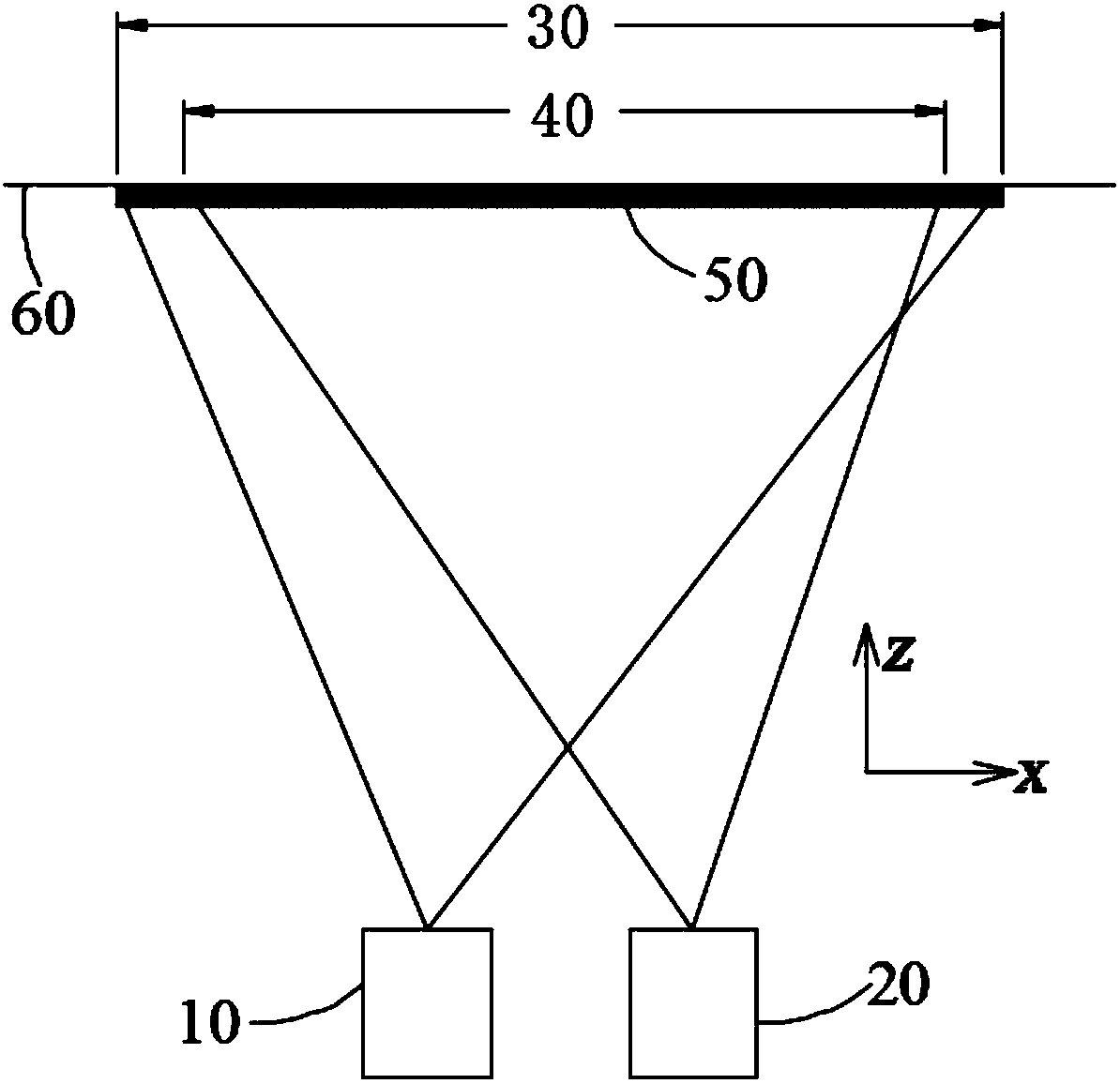
[0033] figure 1 It is a schematic diagram of a structured light depth camera according to an embodiment of the present invention. The depth camera includes a structured light projection module 10 and a collection module 20. The structured light projection module 10 is used to project structured light beams into space. When the structured light beams irradiate the plane 60, structured light will be generated on the area 30 Pattern 50, the collection module 20 is used to collect structured light images on objects in its collection area 40. Generally, the projection area 30 is not smaller than the collection area 40 to ensure that the objects in the collection area corresponding to the collection module can be structured Covered by light patterns.
[0034] When the structured light pattern irradiates the surface of the object, the 3-dimensional shape of the object surface will deform the structured light pattern relative to the preset pattern, and there is a corresponding relationship between the magnitude of the deformation and the depth of the object. Therefore, when performing depth calculation, the structured light pattern reflected by the object is first matched with the preset pattern (reference structured light image/pattern). The matching calculation here refers to the current structured light image (or reference structured light image). ) Select a certain size sub-region with a certain pixel as the center, such as 7x7, 11x11 pixel size sub-regions, and then search for the most similar sub-region to the sub-region on the reference structured light image (or current structured light image). The difference between the pixel coordinates of the area on the two images is the deviation value; secondly, the corresponding relationship between the deviation value and the depth value can be used to calculate the depth value based on the deviation value, and the depth value of multiple pixels constitutes Depth image. The deviation value here generally refers to the deviation value along the baseline direction. The baseline refers to the central connection between the structured light projection module 10 and the acquisition module 20. In the present invention, the baseline direction is the x direction as an example for description. Therefore, it is generally required that structured light images have very high irrelevance along the baseline direction to prevent mismatching.
[0035] In some embodiments, the structured light depth camera may also include two or more acquisition modules 20. Taking two as an example, the structured light projection module 10 has a view of the two acquisition modules 20 (left and right). The structured light pattern is projected in the field area, and the left and right acquisition modules 20 simultaneously acquire left and right structured light images. Based on the binocular vision algorithm, the depth image can also be obtained by calculating the left and right structured light images; the left and right structured light images can also be obtained separately. The right structured light image and the corresponding reference structured light image are calculated to obtain two depth images. The advantage of this is that in one embodiment, the left and right acquisition modules can be set to have different parameters, such as resolution, Focal length, etc., so that structured light images with different resolutions, field angles, etc. can be acquired at the same time, and further, depth images with different resolutions, field angles, etc. can be acquired at the same time; in one embodiment, The acquired multiple depth images are merged into a depth image with more information.
[0036] The depth calculation function can be implemented by a depth calculation processor configured in the depth camera. The processor can be a dedicated processor such as an SOC, FPGA, etc., or a general-purpose processor. In some embodiments, external computing devices, such as computers, mobile terminals, servers, etc., can also be used. The external computing device receives the structured light image from the acquisition module 20 and then performs depth calculation. The obtained depth image can be directly used for the Other applications of the device.
[0037] In one embodiment, the structured light projection module is used to project infrared spot patterns, the acquisition module is a corresponding infrared camera, and the processor is a dedicated SOC chip. When the depth camera is integrated into other computing terminals as an embedded device, such as computers, tablets, mobile phones, TVs, etc., the functions implemented by the above-mentioned processor can be completed by the processor or application in the terminal, for example, the depth calculation The function is stored in the memory in the form of a software module and is called by the processor in the terminal to realize deep calculation.
[0038] The structured light pattern can be a stripe pattern, a two-dimensional pattern, a speckle pattern (spot pattern), etc. The present invention will take the structured light projection module and its depth camera for emitting the speckle pattern as an example for description. Other types of projection patterns The group and its depth camera can also take advantage of the idea of the present invention.
[0039] figure 2 It is a schematic diagram of a structured light projection module according to an embodiment of the present invention. The structured light projection module 10 includes a light source array 201 composed of a plurality of sub-light sources 202 (for example, a vertical face laser emitter array chip, that is, a VCSEL array chip), a lens 203 and a diffractive optical element DOE204. For convenience, only three sub-light sources are drawn in the one-dimensional x direction in the figure. In actual embodiments, the number of light sources can reach tens or even tens of thousands, and the light sources can also be arranged in two dimensions. It can be regular or irregular.
[0040] The light beam emitted by the light source array 201 can form a patterned light beam corresponding to the arrangement of the light source. The patterned light beam is condensed by the lens 203 and then incident on the DOE204. The DOE204 projects a spot patterned beam into the space, and the spot patterned beam is incident on A spot pattern will be formed on the plane 205. Convergence here means that the lens 203 converges the incident light beam with a certain divergence angle and then emits the light beam with a smaller divergence angle. In the figure, only a single line is used to indicate the propagation of a single beam. For simplicity, the beam is not shown. The width and convergence effects. The lens 203 can be a single lens, a lens combination or a lens array composed of multiple lenses, and in some embodiments is used to collimate the light beam emitted by the light source 201.
[0041] Since each sub-light source can be regarded as an uncorrelated light source, and the interference effect between each other can be ignored, the spot pattern emitted by the projection module 201 meets the linear condition, that is, the spot pattern formed by the projection module 10 can be regarded as The light beams emitted by the sub-light sources in the light source 201 are superimposed on the sub-spot patterns independently formed after the DOE204.
[0042] For simplicity, figure 2 The illustrated embodiment only analyzes the situation that DOE204 forms 3 diffraction orders in the x direction (take -1, 0, and 1 order as examples, and other diffraction orders can also be formed) on the incident beam. More diffraction orders in the x and y directions. The DOE 204 receives the light beam from the lens 203 and diffracts the light beam to form three diffraction orders within the diffraction angle θ. The pattern formed by all the diffraction orders is the sub-spot pattern of the sub-light source. In this embodiment, through the comprehensive design of the DOE diffraction angle θ and the size of the light source array (including the DOE diffraction angle, the angle between adjacent diffraction orders, the size of the light source array, the focal length of the lens, and the incidence of each sub-light source relative to the DOE Angle, etc.), so that the sub-spot patterns of multiple sub-light sources cross each other, and the spots of the same order in different sub-spot patterns are focused together to form a spot block. In the figure, the spot block 206 is composed of the first-order diffraction spots, and the zero-order diffraction spots The spots constitute a spot block 207, and the -1st order diffraction spots constitute a spot block 208, and a plurality of spot blocks are arranged in a flat pattern to form a structured light spot pattern. according to figure 2 As shown, it is understandable that the spots and arrangement in each spot block correspond to the arrangement of the sub-light sources 202 in the light source 201, such as the arrangement pattern is the same or in a center-symmetric relationship, etc., and the arrangement of the spot blocks is the same as that in the sub-spot pattern. The spots are arranged in the same way.
[0043] In order to make the density of the spot distribution in the structured light spot pattern relatively uniform and meet the irrelevance, on the one hand, the arrangement of the sub-light sources 202 is designed so that the spot arrangement inside the spot block 206 meets the irrelevance, and on the other hand, the DOE204 The design is such that each spot block 206 is arranged in a tiled manner to ensure that all the spot blocks can cover the entire projection area.
[0044] Figure 4 It is a schematic diagram of a light source arrangement, sub-spot pattern, and structured light spot pattern according to an embodiment of the present invention. Figure 4 (a), (b) and (c) correspond to figure 2 In the illustrated embodiment, the light source 201 in the projection module 10, the sub-spot pattern formed by the DOE 204 of a single beam, and the structured light spot pattern are shown. Figure 4 In (a), the light source includes a substrate 401 and a light source array formed by sub-light sources 402 arranged on the substrate 401. In this embodiment, the sub-light sources in the sub-light source 402 array are arranged irregularly, and the sub-spots The spot distribution in the pattern is a regular distribution, so that the arrangement of each spot block 405 in the finally formed structured light pattern is also regularly arranged as the arrangement of each spot in the sub-spot pattern. In this embodiment, the outline of the arrangement pattern formed by each sub-light source 402 (indicated by a dotted line in the figure, the outline may not be included in the actual product) is an irregular outline, so the outline of each spot block 405 is also irregular Contour, when the spot blocks 405 form a structured light spot pattern 404 in a tiled manner adjacent to each other, the edges of the adjacent spot blocks 405 are irregular ( Figure 4 The undulating non-linear shape is shown in the figure), and adjacent spots are coupled with each other (it should be noted that the actual structured light spot pattern will be deformed due to the distortion of the lens, which is not the ideal situation in the figure). The contour of the spot block 405 is non-linear along the x and/or y direction. It can be understood that because the edge of the adjacent spot block is non-linear, it must not coincide with the baseline, that is, it is inconsistent with the baseline direction x. Compared with the case where the pattern of the sub-light sources 402 is arranged in a square shape, the arrangement manner of mutual coupling between blocks when the contour is non-linear can further improve the irrelevance and density uniformity of spots adjacent to adjacent blocks. in Figure 4 In (c), a structured light spot pattern 404 is formed by a plurality of spot blocks 405 in a tiled arrangement adjacent to each other. In order to facilitate the connection between the spot blocks 405, a dotted line is drawn to indicate the outline, leading to the connection place It is denser, there is no dotted line in the actual pattern, and the density of the connection will be relatively uniform.
[0045] From Figure 4 It can be seen in (c) that the arrangement form of mutual coupling between non-linear contours can improve the randomness of the spot distribution at the junction of adjacent blocks. However, the unfavorable factor is that non-straight lines will also appear at the edges of the structured light spot pattern. For the undulating outline, because the field of view of the acquisition module is often square (here we still analyze under ideal conditions, ignoring image distortion), the effective area 406 of the structured light spot pattern is smaller than the overall structured light spot composed of all the spot blocks 405 Pattern 404.
[0046] image 3 It is a schematic diagram of a structured light projection module according to another embodiment of the present invention. The light source array 301 composed of a plurality of sub-light sources 302 emits light beams after being condensed by the lens 303 and incident on the DOE 304 to emit a structured light spot pattern on the plane 305. versus figure 2 The difference in the illustrated embodiment is that the diffraction angle θ of DOE304 in this embodiment is relatively small, so that the sub-spot patterns formed by the light beams emitted by each sub-light source after being diffracted by DOE304 do not cross each other, that is, a spot block is directly formed. Such as image 3 As shown in the figure, the sub-spot patterns formed by the sub-light sources 3021, 3022, 3023 diffracted by DOE304 and composed of spots of different diffraction orders are 308, 307, and 306, respectively. versus figure 2 The difference in the illustrated embodiment is that the multiple sub-spot patterns do not cross and form a structured light spot pattern. From image 3 It can be seen that the arrangement of the multiple sub-spot patterns corresponds to the arrangement of the sub-light sources 302.
[0047] Figure 5 It is a schematic diagram of light source arrangement, sub-spot pattern and structured light spot pattern according to another embodiment of the present invention. Figure 5 (a), (b) and (c) correspond to image 3 In the illustrated embodiment, the light source 301 in the projection module 10, the sub-spot pattern formed by the DOE 304 of a single beam, and the structured light spot pattern are shown. Figure 5 (a) The light source is composed of a substrate 501 and sub-light sources 502. The sub-light sources 502 are arranged regularly so that the sub-spot patterns are arranged in a tiled arrangement to cover the projection area to form a structured light spot pattern, such as Figure 5 (c) Shown; Figure 5 (b) A sub-spot pattern 503 composed of multiple diffraction orders after the light beam emitted by a single sub-light source is diffracted by DOE304; Figure 5 Shown in (c) is a structured light spot pattern 504, which is composed of a plurality of sub-spot patterns 505 (ie, sub-spot patterns 503), and the arrangement of the sub-spot patterns 505 corresponds to the arrangement of the sub-light sources 502. In this embodiment, in order to make the structured light spot pattern meet the irrelevance characteristic, the arrangement of the spots in the sub-spot pattern (spot block) 503 is irregular. This requirement can be designed by designing the DOE304 to make adjacent diffraction orders It is realized by the uneven distribution of the included angle of the light beam. In this embodiment, the contour of the sub-spot pattern 503 is non-linear along the x and/or y direction, and adjacent sub-spot patterns are coupled with each other to form a structured light spot pattern.
[0048] It should be noted, Figure 4 , Figure 5 Each pattern in is a schematic description, and the proportion of the pattern is not strictly in accordance with the actual product design. The tiling arrangement mentioned here is to arrange a plurality of sub-patterns in a non-overlapping form, and form the final pattern to basically cover the field of view area. The tiling arrangement includes not only adjoining the sub-patterns, but also Arrange with a certain gap, see the following embodiments for details.
[0049] Image 6 It is a schematic diagram of a structured light spot pattern according to an embodiment of the present invention. In some embodiments, in order to further expand the projection area of the projection module, when a plurality of spot blocks 602 (or sub-spot patterns) form the structured light spot pattern 601 in a tiled arrangement, the adjacent blocks are coupled to each other. They are no longer adjacent, but staggered by a certain gap 603. However, it is not that the larger the gap, the better. It can be understood that when the gap is increased, the blank area in the sub-region will be larger when the matching calculation is performed, which will reduce the accuracy of the depth value or fail to calculate the depth value. Such as Picture 9 As shown in the neutron region 903 and the sub region 906, there are only a few spots in the region. Therefore, the size of the gap generally needs to be set in conjunction with the size of the sub-region 604 in the depth calculation algorithm.
[0050] When the edge shape of the spot block 602 is non-straight, since the size of the sub-region 604 is generally square, that is, its edge shape is a straight line. When sub-region selection and matching calculation are performed on the pixels around the gap, the sub-region 604 can all contain The spots in the adjacent spot blocks can thereby increase the degree of irrelevance of the sub-regions around the gap. When the edge shape of the spot block 602 is a straight line, there will be a large number of sub-regions around the gap that only contain the spots in a single block and blank gaps. At this time, the degree of irrelevance of the spot arrangement in the sub-regions is low.
[0051] In addition to improving the irrelevance of the sub-regions, the irregular edge shape can also increase the area of the projection area. Picture 9 Shown is a schematic diagram of the relationship between sub-regions and gaps between blocks according to an embodiment of the present invention. When the size of the sub-area is constant (the size of the sub-area determines the accuracy and efficiency of the depth calculation algorithm, so a compromise value is generally selected), for the case where the blob is square, such as Picture 9 As shown in (a), the adjacent spot blocks 901 and 902 are square, and their contours are parallel to one side of the sub-region. In order to make the spots exist in the sub-region, theoretically the side length h of the sub-region is not less than between the adjacent spot blocks The gap g1 (in fact, it should be much smaller than the side length of the sub-region, for example, set to half of the side length), that is, h≥g1; however, when the edge contour is a non-linear blob, such as Picture 9 As shown in (b), the gap g2 between adjacent spots is not necessarily required to be smaller than the side length h of the subregion. Compared Picture 9 (a) and Picture 9 (b), it can be clearly seen that g2> g1, that is, for a patch surface with a non-linear contour, when the size of the sub-region is constant, the gap between adjacent spots is relatively large, so a larger field of view can be obtained. On the contrary, when the gap is the same, the structured light spot pattern composed of the non-straight contour spot block can be used in the matching calculation, which can use a smaller matching sub-region, which can speed up the matching calculation speed, thereby improving the depth image The output frame rate.
[0052] In order to further improve the irrelevance of the pattern, the adjacent spots can also be arranged in a staggered manner, such as Figure 7 Shown. in Figure 7 In this case, the adjacent spots 702 and 705 are arranged in a staggered arrangement along the y direction, thereby improving the degree of irrelevance between the blocks along the x direction of the baseline. in Figure 7 In the illustrated embodiment, there are gaps 703 between adjacent blocks. It can be understood that a staggered arrangement scheme can also be used in embodiments without gaps.
[0053] Figure 4 as well as Figure 5 In the illustrated embodiment, Figure 4 Set the sub-light source arrangement pattern to a non-linear edge, Figure 5 The sub-spot pattern is arranged in a non-straight edge form, so that adjacent blocks of the multiple blocks constituting the structured light spot pattern are coupled to each other, thereby improving the degree of irrelevance of the structured light spot pattern. In addition to the spot pattern shown in the figure, there can also be many other patterns, such as wavy edges. It can be understood that when the edges are non-straight lines, the adjacent edges of adjacent blocks must be inconsistent with the baseline direction, and adjacent edges of adjacent blocks can be coupled with each other. In addition, when the edges are straight lines, the adjacent edges of adjacent blocks may also be inconsistent with the baseline direction, and adjacent edges of adjacent blocks are coupled with each other. such as Figure 8 It is a schematic diagram of a structured light pattern according to another embodiment of the present invention. The structured light pattern 801 is composed of a plurality of spot blocks 802 (or sub-spot patterns). The spot blocks are in a prismatic shape, and adjacent blocks are coupled with each other. A sub-area is arbitrarily selected around any gap in the effective area 803. The sub-regions all contain spots in at least two blocks, so the structured light spot pattern has a high degree of irrelevance.
[0054] In some applications, it is often necessary to obtain high-resolution depth images. At this time, projecting a higher-density speckle pattern will facilitate the acquisition of high-resolution depth images.
[0055] Picture 10 It is a schematic diagram of a structured light projection module for projecting high-density patterns according to an embodiment of the present invention. The projection module 10 includes a light source array 1001 composed of a plurality of sub-light sources 1002, a lens 1003 and a DOE 1004, and figure 2 When the illustrated embodiment is different, the structured light spot pattern formed by the beam emitted by DOE 1004 incident on the plane 1005 is relatively figure 2 The structured light spot pattern in has a higher density. figure 2 The spot blocks composed of spots of the same diffraction order are arranged in a tiled arrangement (adjacent or arranged with appropriate gaps) to form a structured light spot pattern. In this embodiment, the spots are overlapped to increase the density of the spots. distributed. Picture 10 The structured light spot pattern formed by overlapping the spot blocks 1006 of six different diffraction orders (taking -2, -1, 0, 1, 2, and 3 orders as examples) is schematically shown in.
[0056] In fact, not any form of overlap can produce a structured light spot pattern that can be used for depth calculation. This is because in order to calculate a depth image, the density distribution of the structured light spot pattern will also affect its irrelevance. Influencing the calculation of the depth image, the structured light spot pattern with relatively uniform density distribution is the most ideal. Therefore, while increasing the pattern density by overlapping, it is also necessary to ensure the uniformity of the density distribution as much as possible.
[0057] In order to make the pattern density relatively uniform, the present invention proposes an overlapping scheme. In order to facilitate the display of the overlapping scheme, a plurality of spots 1006 with different diffraction orders on the plane 1005 are staggered in the z direction in the figure. It can be understood that, in fact, all the spots are formed on the plane 1005. In such Picture 10 In the illustrated embodiment, the three spot blocks with diffraction orders of 2, 0, -2 are adjacent to each other to form the first structured light spot pattern, and the three spot blocks with diffraction orders of 3, 1, and -1 pass through Adjacent to each other to form the second structured light spot pattern, the first structured light spot pattern and the second structured light spot pattern are staggered at a certain distance and overlap each other. The overlapping area of the two sub-structured light spot patterns is 1007, This area is also the effective projection area of the projector 10, and the density of the non-overlapping edge area is lower than that of the overlapping area. Since each sub-spot structured light spot pattern is composed of multiple spot blocks adjacent to each other, its density distribution is relatively uniform. When multiple uniform sub-spot structured light patterns are overlapped in a staggered manner, the density of the spot pattern in the overlapping area The distribution is also relatively uniform. Therefore, this overlapping scheme will help generate structured light spot patterns with a relatively uniform density distribution.
[0058] Picture 12 It is a schematic diagram of an overlapping pattern according to an embodiment of the present invention. in Picture 11 Only a one-dimensional overlap scheme is schematically given in, for further illustrative illustration, Picture 12 An overlap scheme in two dimensions is given. Picture 12 (a) shows the first structured light spot pattern 1201 composed of 9 different diffraction orders (corresponding to the horizontal and vertical coordinates in the figure). Picture 12 (b) shows the second structured light spot pattern 1202 composed of 9 spot blocks, Picture 12 (c) is a structured light spot pattern formed by staggering the first and second structured light spot patterns. The second structured light spot pattern is offset from the first structured light spot pattern along the first direction (x) and the second direction (y) perpendicular to the first direction by distances Sx and Sy, respectively. It can be understood that the two sub-structured light spot patterns can also only be offset by a certain distance in the x or y direction to achieve mutual overlap. When two sub-structured light spot patterns overlap in a single direction (for example, the x direction or the y direction), the density in the corresponding direction will increase. The density in the overlapping area 1203 is increased relative to the density in the edge non-overlapping area. As shown in the pattern density distribution diagrams in the enlarged diagrams 1204 and 1205, the overlapping area 1203 is the effective projection area.
[0059] in Picture 12 In the illustrated embodiment, each spot block in the sub-structured light spot pattern is composed of being adjacent to each other, Figure 13 An example of another overlapping scheme is given. In this example, a certain gap is set between the spot blocks in the sub-structured light spot pattern to increase the projected area. Figure 13 (a) shows the first structured light spot pattern 1301 composed of spots with 9 different diffraction orders (corresponding to the horizontal and vertical coordinates in the figure). Figure 13 (b) shows the second structured light spot pattern 1302 composed of 9 spot blocks, Figure 13 (c) is a structured light spot pattern formed by staggering the first and second structured light spot patterns. It can be seen from the figure that the first and second structured light spot patterns are both formed by multiple spot blocks arranged with a certain gap.
[0060] Picture 12 versus Figure 13 In the illustrated embodiment, it is schematically shown that two sub-structured light spot patterns are overlapped to produce a high-density and uniformly distributed structured light spot pattern. According to this inventive idea, it is conceivable that two or two It is also feasible to overlap more than one sub-structured light spot pattern to generate a higher density structured light spot pattern. Figure 14 Shown is a schematic diagram of a structured light spot pattern generated by overlapping three sub-structured light spot patterns according to an embodiment of the present invention. Here with Figure 14 (a) shows the first structured light spot pattern 1401 composed of spots with 9 different diffraction orders (corresponding to the horizontal and vertical coordinates in the figure). Figure 14 (b) shows the second structured light spot pattern 1402 composed of 9 spot blocks, Figure 14 (c) shows the third structured light spot pattern 1403 composed of 9 spot blocks, Figure 14 (d) is a structured light spot pattern formed by staggered arrangement of the first, second and third structured light spot patterns. The common area 1404 where the three sub-structured light spots overlap has the highest density.
[0061] Figure 12-14 For illustrative purposes only, in fact, the distance of misalignment is very small relative to the entire field of view, that is, non-overlapping areas with low edge density or small overlap (such as Figure 14 The area shown where the two sub-structured light spot patterns overlap) is much smaller than the effective projection areas 1203, 1303, and 1404.
[0062] Picture 11 What is shown is a schematic diagram of a structured light projection module for projecting high-density patterns according to another embodiment of the present invention. This embodiment is relative to image 3 In the illustrated embodiment, the multiple sub-structured light spot patterns 1106 constituting the structured light spot pattern are overlapped in a certain overlapping manner to form a high-density structured light spot pattern. In this embodiment, five sub-light sources 1102 arranged in sequence along the x direction are taken as an example for description. The five sub-light sources 1102 generate sub-structured light spot patterns a, b, c, d, and e via a lens 1103 and a DOE 1104, respectively. The sub-spot patterns a, c, and e are arranged in a tiled arrangement (that is, adjacent to each other or arranged in a gap) to form the first structured light spot pattern, and the sub-spot patterns b and d are arranged in a tiled manner to form the second structure. Light spot pattern, the first structured light spot pattern and the second structured light spot pattern overlap with a certain offset to form the final structured light spot pattern. The density of the overlapping area 1107 is increased relative to any structured light spot pattern. The area 1107 is the effective projection area of the projection module 10. Multiple sub-structured light spot patterns overlapping each other to produce a high-density structured light spot pattern can also be as Figure 12-14 Overlapped form, but Figure 12-14 The blobs in are sub-spot patterns in this embodiment.
[0063] The size of multiple sub-structured light spot patterns can be the same (such as Picture 10 Shown in the embodiment) can also be different (such as Picture 11 As shown in the illustrated embodiment), in actual applications, it can be configured according to requirements. For example for Picture 11 In the illustrated embodiment, a first structured light spot pattern can be configured first, and the pattern is designed to correspond to the effective projection area (for example, Picture 11 In the effective projection area 1107 composed of sub-spot patterns b and d), another second structured light spot pattern (for example, Picture 11 In the area composed of sub-spot patterns a, c, and e), since the sub-spot patterns that make up each sub-structured light spot pattern are composed of a single light source through DOE diffraction, so when configuring, the first time the area is smaller The number of light sources required by the structured light spot pattern should be less than the number of light sources corresponding to the second structured light spot pattern. Compared with the situation where multiple sub-structured light spot patterns have the same size, this embodiment can reduce the number of light sources, thereby reducing power. Consumption.
[0064] Understandably, Figure 10 ~ Figure 14 In the illustrated embodiment, the light source arrangement pattern (spot block) and the contour shape of the sub-spot pattern can also be set as Figure 4 ~ Figure 8 Non-linear form in the illustrated embodiment.
[0065] for figure 2 versus Picture 10 In the illustrated embodiment, the structured light spot pattern is composed of spot blocks, and each spot block is composed of the same diffraction order of multiple sub-light sources. It can be understood that when multiple sub-light sources are configured to be controlled independently or in groups, The size of the projection area of the structured light spot pattern will not change, but the density of the pattern will change. The more the number of sub-light sources turned on, the greater the density. Therefore, in some embodiments, the multiple light sources in the light source array can be divided into multiple sub-arrays. The sub-arrays can be arranged in a cross or tiling arrangement in space. During projection, the switch of the sub-array can be controlled. Can produce different density structured light spot pattern projection, which can be adapted to different applications.
[0066] for image 3 versus Picture 11 In the illustrated embodiment, the structured light spot pattern is composed of sub-spot patterns, where the sub-spot pattern is formed by a single sub-light source in the array light source. Therefore, independent or grouped control of the sub-light sources in the light source array will directly affect The size or density of the projection area will be described below in conjunction with specific embodiments.
[0067] For example, based on image 3 Show the principle and as Figure 5 In the structured light spot pattern forming embodiment shown, if the multiple sub-light sources 502 in the light source array are grouped and controlled, for example, the sub-light sources in the middle area 507 are grouped to form the first sub-light source array, and the surrounding sub-light sources are one The group forms the second sub-light source array, so that two projection effects with different projection pattern areas can be generated. When only the first sub-light source array is turned on, it forms as Figure 5 The first structured light spot pattern corresponding to the area 508 in (c); and when the first sub-light source array and the second sub-light source array are turned on at the same time, it can be formed as Figure 5 The structured light spot pattern 504 in (c). This setting can better save power consumption. For example, for some applications with a small field of view, only a few sub-light sources need to be turned on to meet the demand. In some embodiments, more groups of sub-light source arrays can also be provided, and even each sub-light source can be independently controlled.
[0068] For another example, for Picture 11 In the illustrated embodiment, independent or grouped control of the sub-light sources in the light source array can not only change the size of the projection pattern area, but also change the pattern density. Assuming that the sub-light sources 1102 are marked as A, B, C, D, and E from bottom to top in the figure (not shown in the figure), the sub-structured light spot patterns generated by them are respectively a, b, c, d, and e. If the sub-light sources A, C, and E are grouped into a group to form the first sub-light source array, and the sub-light sources B and D form a group to form the second sub-light source array, when only the first sub-light source array is turned on, the sub-structure The light spot patterns a, c, and e have an area S1 and a first structured light spot pattern with a distribution density of D1; when only the second sub-light source array is turned on, it will produce a sub-structured light spot pattern b, d A second structured light spot pattern with an area of S2 and a distribution density of D2; when the first sub-light source array and the second sub-light source array are turned on at the same time, the sub-structured light spot patterns a, b, c, d, e will be generated The composition area is S3 (referring to the effective projected area) and the third structured light spot pattern with a distribution density of D3. It can be seen from the figure:
[0069] S1> S2=S3,
[0070] D1=D2
[0071] Based on this idea, in some embodiments, the light source array may also have other forms of grouping or independent control, which will not be illustrated here. Therefore, in this embodiment, the sub-light sources in the light source array can be controlled independently or in groups to project structured light spot patterns of various areas and various densities.
[0072] The above content is a further detailed description of the present invention in combination with specific/preferred embodiments, and it cannot be considered that the specific implementation of the present invention is limited to these descriptions. For those of ordinary skill in the technical field to which the present invention belongs, without departing from the concept of the present invention, they can also make several substitutions or modifications to the described embodiments, and these substitutions or modifications should be regarded as It belongs to the protection scope of the present invention.
Login to view more PUM


Description & Claims & Application Information
We can also present the details of the Description, Claims and Application information to help users get a comprehensive understanding of the technical details of the patent, such as background art, summary of invention, brief description of drawings, description of embodiments, and other original content. On the other hand, users can also determine the specific scope of protection of the technology through the list of claims; as well as understand the changes in the life cycle of the technology with the presentation of the patent timeline. Login to view more.
Login to view more Similar technology patents
Uniform delivery of compositions
Owner:THE PROCTER & GAMBLE COMPANY
Fuel-Cell Stack And Fuel Cell
ActiveUS20080113243A1Reduce variationEvenly distributedFuel cells groupingFuel cell auxillariesMembrane configurationAirflow
Owner:PANASONIC CORP
Hair drying device
Owner:HADDEN DAVID M
Carotenoid preparation and use thereof and feedstuff containing the preparation and preparation method thereof
ActiveCN101396068AIncrease fuel capacityEvenly distributedOrganic active ingredientsCosmetic preparationsAnimal feedChemistry
Owner:ZHEJIANG MEDICINE CO LTD XINCHANG PHAMACEUTICAL FACTORY
Fracturing fluid and fracturing method for increasing applicaiton efficiency of support agent in fractured cracks
ActiveCN103013486AReduce sedimentation rateEvenly distributedFluid removalDrilling compositionGuar gumEnvironmental geology
Owner:PETROCHINA CO LTD +1
Classification and recommendation of technical efficacy words
- Improve density distribution
- Evenly distributed
A crowd counting method and system based on a spatial perception attention refinement framework
PendingCN109558862AImprove density distributionCharacter and pattern recognitionSpatial regressionDensity distribution
Owner:拓元(广州)智慧科技有限公司
Array substrate and light field display device
ActiveUS20210265444A1Small sizeImprove density distributionStatic indicating devicesSolid-state devicesSignal linesElectrode pair
Owner:BOE TECH GRP CO LTD
Layout structure
InactiveUS20080099790A1Improve density distributionReduced coupling capacityCross-talk/noise/interference reductionSemiconductor/solid-state device detailsEngineering
Owner:INFINEON TECH AG
Preparation method of foaming agent for use in burning of refractory brick
Owner:港泰耐火材料(江苏)有限公司
Image denoising method based on generative adversarial networks
InactiveCN108765319AEasy to trainEvenly distributedImage enhancementImage analysisGenerative adversarial networkImage denoising
Owner:DALIAN UNIV OF TECH
Drug-eluting stent (DES) with multicoating
Owner:SHANGHAI MICROPORT MEDICAL (GROUP) CO LTD
Mould for making glass container
ActiveCN101298355AIncrease temperatureEvenly distributedVacuum and blow machinesGlass containerMaterials science
Owner:CHANGSHU WEIHENG MOLD MFG