Pixel compensation circuit, pixel driving circuit compensation method, and display device

A technology of pixel driving circuit and compensation method, which is applied to static indicators, instruments, etc., can solve the problems of small pixel compensation range, inability to perform compensation in real time, and low compensation accuracy.

Inactive Publication Date: 2018-09-04
BOE TECH GRP CO LTD
View PDF4 Cites 10 Cited by
  • Summary
  • Abstract
  • Description
  • Claims
  • Application Information

AI Technical Summary

Problems solved by technology

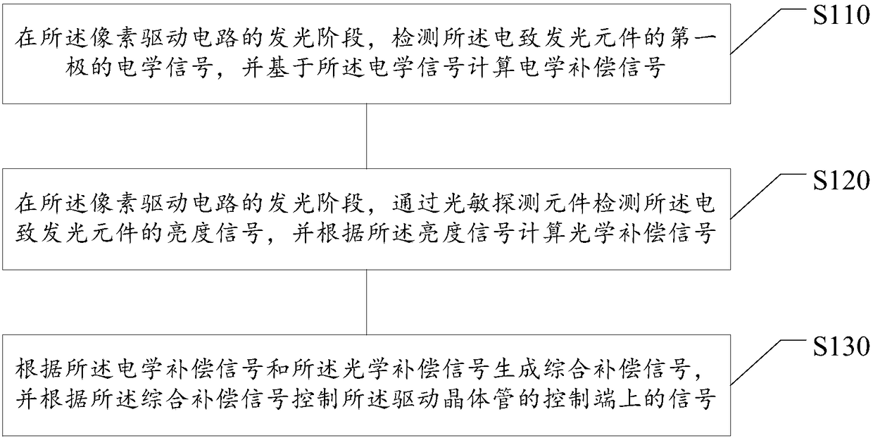
[0006] The purpose of the present disclosure is to provide a pixel compensation circuit, a compensation method for a pixel driving circuit, and a display device, so as to overcome the problems of small pixel compensation range, relatively low compensation accuracy, and inability to perform real-time compensation at least to a certain extent.

Method used


Image

  • Pixel compensation circuit, pixel driving circuit compensation method, and display device
  • Pixel compensation circuit, pixel driving circuit compensation method, and display device
  • Pixel compensation circuit, pixel driving circuit compensation method, and display device

Examples


Embodiment Construction

[0046]Example embodiments will now be described more fully with reference to the accompanying drawings. Example embodiments may, however, be embodied in many forms and should not be construed as limited to the embodiments set forth herein; rather, these embodiments are provided so that this disclosure will be thorough and complete, and will fully convey the concept of example embodiments to those skilled in the art. The described features, structures, or characteristics may be combined in any suitable manner in one or more embodiments. In the following description, numerous specific details are provided in order to give a thorough understanding of embodiments of the present disclosure. However, those skilled in the art will appreciate that the technical solutions of the present disclosure may be practiced without one or more of the specific details, or that other methods, components, materials, devices, steps, etc. may be employed. In other instances, well-known technical so...


PUM


Abstract

The disclosure relates to the technical field of displaying, especially to a pixel compensation circuit, a pixel driving circuit compensation method, and a display device. The pixel driving circuit compensation method comprises: at a light-emitting stage of a pixel driving circuit, an electrical signal of a first pole of an electroluminescent element is detected and an electrical compensation signal is calculated based on the electrical signal; at a light-emitting stage of a pixel driving circuit, a brightness signal of the electroluminescent element is detected by a photosensitive detecting element and an optical compensation signal is calculated based on the brightness signal; and a comprehensive compensation signal is generated according to the electrical compensation signal and the optical compensation signal and a signal of a control terminal of a drive transistor is controlled based on the comprehensive compensation signal. The compensation range is large, the compensation precision is high, and the driving speed is fast; and real-time compensation of the electroluminescent element is realized to ensure the uniformity of display brightness of all pixels.

Description

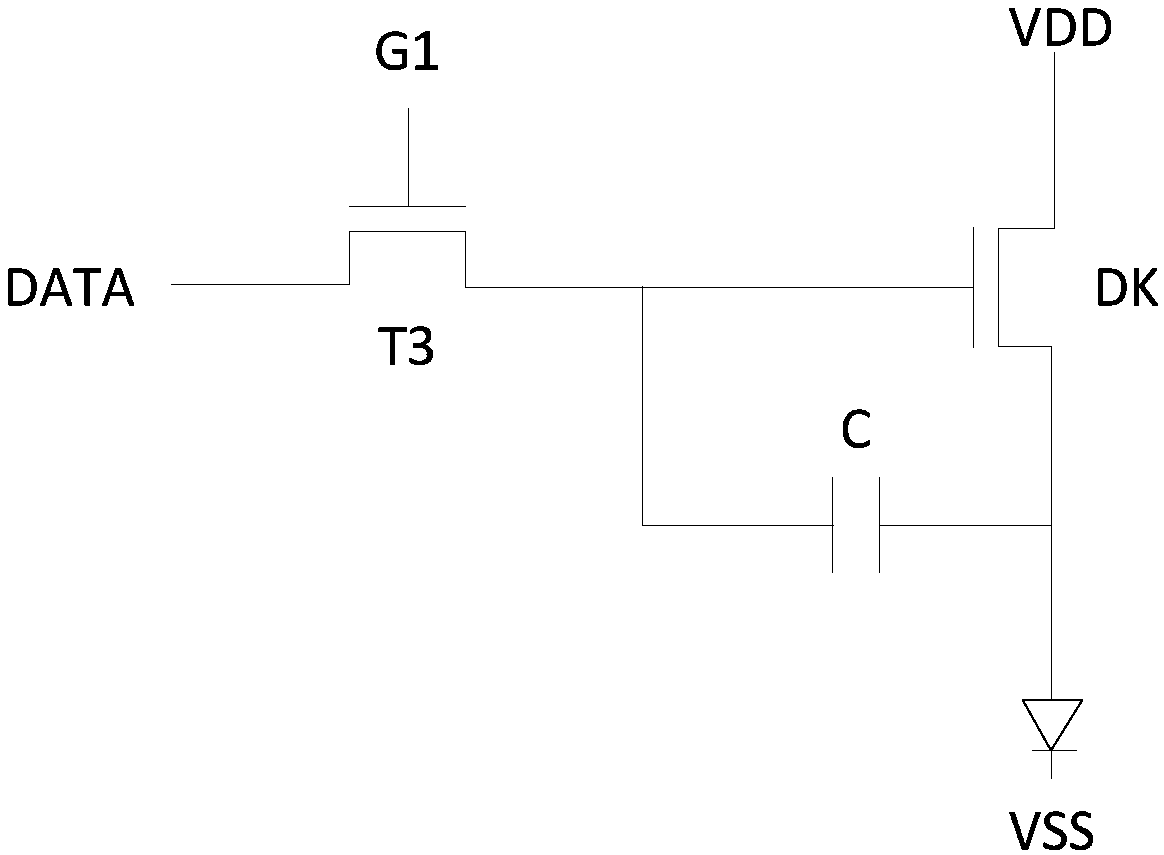
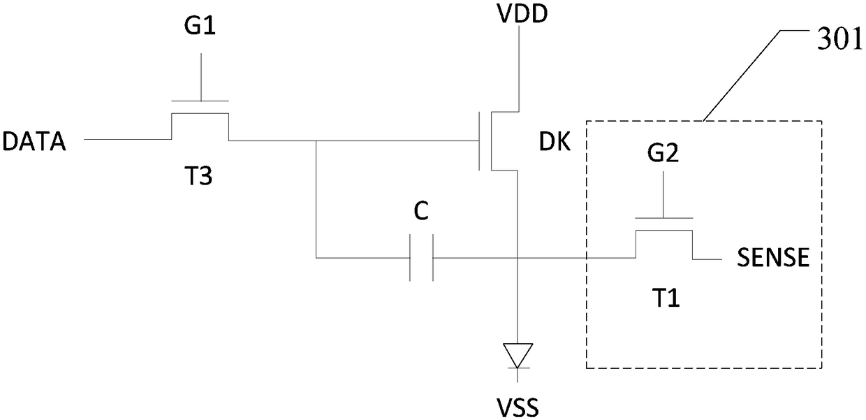
technical field [0001] The present disclosure relates to the field of display technology, and in particular, to a pixel compensation circuit, a compensation method for a pixel driving circuit, and a display device. Background technique [0002] In the pixel driving circuit, due to the instability of the manufacturing process, there are differences in the threshold voltage, mobility, driving voltage of the electroluminescent element, etc. of the driving transistor among multiple pixels, resulting in the driving current of the electroluminescent element The difference makes the luminance of the electroluminescent elements in each pixel unit inconsistent, which further reduces the brightness uniformity of the display screen, and even produces afterimages such as regional spots and images. [0003] At present, commonly used methods for compensating pixels include internal compensation and external compensation, wherein external compensation includes external electrical compensat...

Claims


Application Information

Patent Timeline
Patent Type & Authority Applications(China)
IPC IPC(8): G09G3/32G09G3/30
CPCG09G3/30G09G3/32G09G2300/0819G09G2300/0842G09G2320/0233G09G2320/0295G09G2360/145G09G2360/147
Inventor 盖翠丽林奕呈王玲徐攀
Owner BOE TECH GRP CO LTD
Why Eureka
Try Eureka