Heat dissipation assembly for cavity filter

A cavity filter and heat dissipation component technology, which is applied in the filter field, can solve the problem that the filter cannot meet the circuit structure, etc., and achieve the effect of facilitating convection, enhancing heat dissipation performance, and helping heat dissipation

Inactive Publication Date: 2018-09-04
CHENGDU XUSITE TECH CO LTD
View PDF0 Cites 0 Cited by
  • Summary
  • Abstract
  • Description
  • Claims
  • Application Information

AI Technical Summary

Problems solved by technology

[0003] The technical problem to be solved by the present invention is that the current structure of the heat sink of the filter cannot meet the complex circuit structure of today, and the purpose is to provide a heat sink for the filter cavity, so as to solve the problem that the structure of the current heat sink of the filter cannot meet the requirements of today's complex circuit structure. The problem of the circuit structure

Method used


Image

  • Heat dissipation assembly for cavity filter

Examples


Embodiment 1

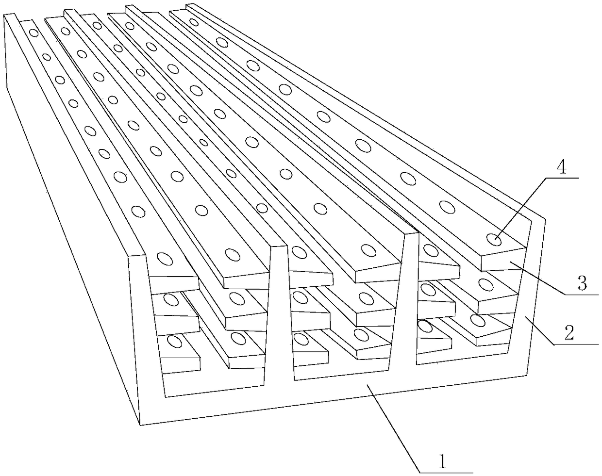
[0019] like figure 1 As shown, this embodiment includes a housing 1, heat sinks 2 uniformly distributed on the outer surface of the housing 1, auxiliary heat sinks 3 located on both sides of the heat sink 2, and a plurality of heat dissipation holes 4 are uniformly arranged on the auxiliary heat sink 3 A plurality of auxiliary cooling fins 3 are evenly distributed on both sides of the cooling fin 2, and the central axes of the cooling holes 4 on the plurality of auxiliary cooling fins 3 correspond to each other on a straight line. The auxiliary cooling fins 3 form a heat dissipation unit, and there are gaps between the cooling units, and the gap distance is 0.4 cm to 0.7 cm. During implementation, the material used for the cooling fins 2 and the auxiliary cooling fins 3 is aluminum. When installing the heat sink, the height of the heat sink can be adjusted according to the needs to enhance its heat dissipation performance. After increasing the height of the heat sink, add mult...


PUM


Abstract

The invention discloses a heat dissipation assembly for a cavity filter. The heat dissipation assembly comprises a shell, wherein heat dissipation fins are uniformly distributed on the outer surface of the shell, auxiliary heat dissipation fins are located on two sides of the heat dissipation fins, a plurality of heat dissipation holes are uniformly formed in the auxiliary heat dissipation fins, the auxiliary heat dissipation fins are uniformly distributed on two sides of the heat dissipation fins, and the central axes of the heat dissipation holes in the auxiliary heat dissipation fins are mutually and correspondingly located on the same straight line; a heat dissipation unit is formed by one heat dissipation fin and multiple auxiliary heat dissipation fins on the heat dissipation fin, and a gap is formed between each two heat dissipation units and is 0.4cm-0.7cm; and the heat dissipation fins and the auxiliary heat dissipation fins are prepared from aluminum while implementing. Whenthe heat dissipation fins are arranged, the heights of the heat dissipation fins can be adjusted according to the requirements, so that the heat dissipation performance of the heat dissipation fins isimproved; and after the heat dissipation fins are heightened, the auxiliary heat dissipation fins are simultaneously arranged on two sides of the heat dissipation fins so as to increase the heat dissipation areas, so that the heat dissipation performance of the heat dissipation fins is improved.

Description

technical field [0001] The invention relates to a filter, in particular to a heat dissipation component for a cavity filter. Background technique [0002] With the development and progress of electronic technology, the simple circuit structure can no longer meet the needs. Today's circuit structure is becoming more and more complex, and more and more electronic products require more and more data to be transmitted, making the system structure more and more complicated. Therefore, the design of the heat dissipation system is getting more and more attention. Faced with this development trend, it is inevitable to design a new type of heat dissipation device. Contents of the invention [0003] The technical problem to be solved by the present invention is that the current structure of the heat sink of the filter cannot meet the complex circuit structure of today, and the purpose is to provide a heat sink for the filter cavity, so as to solve the problem that the structure of ...

Claims


Application Information

Patent Timeline
Patent Type & Authority Applications(China)
IPC IPC(8): H01P1/207H01P1/30
CPCH01P1/207H01P1/30
Inventor 王东罗志刚宋旭
Owner CHENGDU XUSITE TECH CO LTD
Why Eureka
Try Eureka