Slide block plastic injection structure

A slider and glue feeding technology, which is applied in the field of mold structure, can solve the problems that the glue inlet cannot be increased, the product cannot be formed, and the slider will block the product, etc.

Active Publication Date: 2018-09-07
MITAC PRECISION TECH(KUNSHAN) CORP
View PDF5 Cites 0 Cited by
  • Summary
  • Abstract
  • Description
  • Claims
  • Application Information

AI Technical Summary

Problems solved by technology

Usually there is a slider on the outside of the product 10, the slider will block the product 10, and it is impossible to increase the glue inlet from the middle of the length or width of the product 10, and thus the product 10 c

Method used


Image

  • Slide block plastic injection structure
  • Slide block plastic injection structure
  • Slide block plastic injection structure

Examples


Embodiment Construction

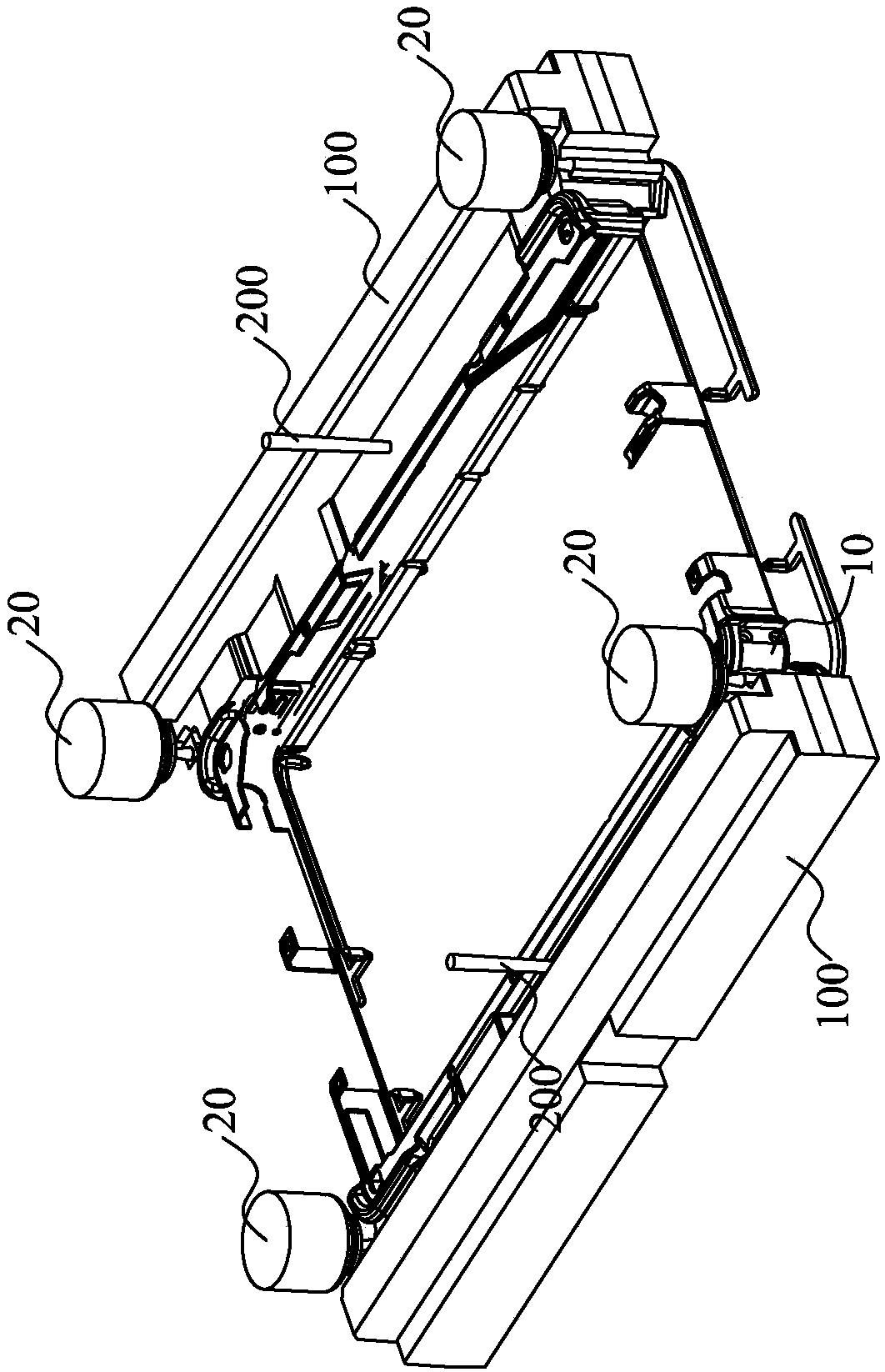
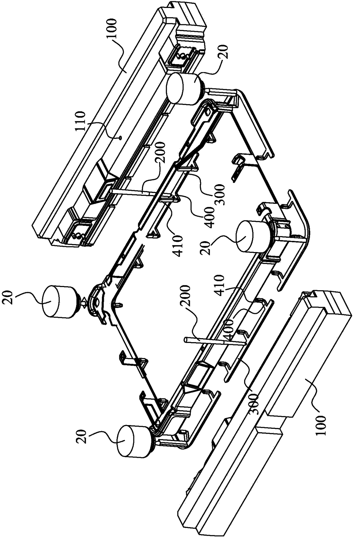
[0021] see Figure 2 to Figure 4 shown, where figure 2 A schematic perspective view of a preferred embodiment of the slider glue feeding structure of the present invention is shown, image 3 An exploded schematic diagram of a preferred embodiment of the slider glue-feeding structure of the present invention is shown, Figure 4 A schematic diagram of a preferred embodiment of the slider glue feeding structure of the present invention in the mold is shown.

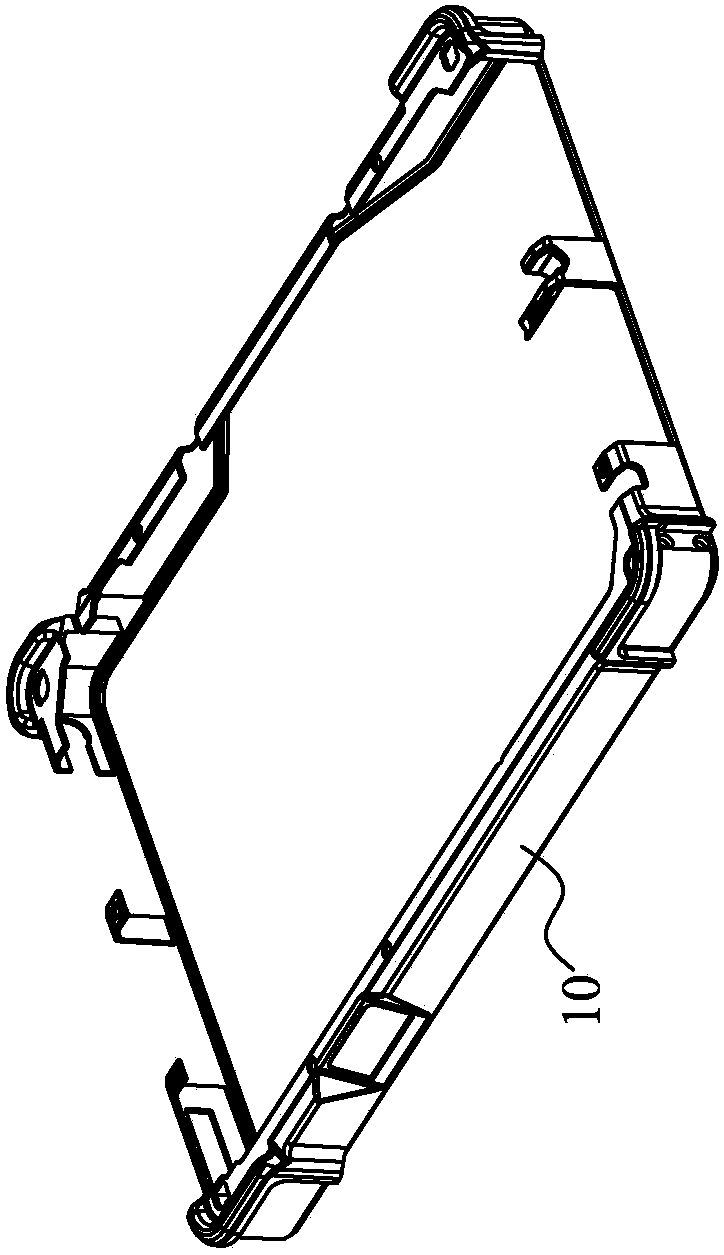
[0022] The slide block glue feeding structure of the present invention is applied in a mold to form a cuboid product 10. The mold is a three-plate mold, and the mold includes a plurality of hot filling nozzles 20, wherein four hot filling nozzles 20 are formed from the product respectively. The four corners of 10 are fed with glue, and the direction of mold opening is taken as the vertical direction, and the structure of the slider with glue feed includes:

[0023] Slide block 100, it is located at the outside of product...


PUM


Abstract

The invention provides a slide block plastic injection structure which is applied to a mold and takes the mold-opening direction of the mold as a vertical direction. The slide block plastic injectionstructure comprises slide blocks, which are arranged on the outer side of a to-be-molded product; vertical runners, with one ends connected with the hot sprues of the mold and the other ends vertically penetrating the slide blocks; transverse runners, which are horizontally arranged on the bottom sides of the slide blocks and communicate with the other ends of the vertical runners; and branch runners, which are diverted from the transverse runners and vertically and upwardly bend from the horizontal direction to form plastic injection ports for plastic injection. According to the slide block plastic injection structure in the invention, the vertical runners are configured to penetrate the slide blocks for plastic injection, and plastic injection ports can be additionally formed in the middle parts of the length or width direction of the product, so the problem that extra plastic injection ports cannot be formed in the middle parts of the length or width direction of products due to shielding of the products by slide blocks in the prior art is overcome.

Description

【Technical field】 [0001] The invention relates to a mold structure, in particular to a sliding block glue feeding structure. 【Background technique】 [0002] When injecting plastic products, if the product is in the shape of a cuboid, such as a laptop case, etc., the glue is usually injected from the four corners of the product. [0003] However, see figure 1 , which depicts a schematic diagram of a product. If the length or width of the product 10 is relatively long, the effect of glue feeding from the four corners is not good, and it is necessary to add glue inlets in the middle of the length or width. Usually, there is a slider on the outside of the product 10, and the slider will block the product 10, so it is impossible to increase the glue inlet from the middle of the length or width of the product 10, and then the product 10 cannot be formed. [0004] In view of this, it is necessary to develop a slider glue feeding structure to solve the problem that the slider wil...

Claims


Application Information

Patent Timeline
IPC IPC(8): B29C45/27
CPCB29C45/27B29C45/2735
Inventor 吴永兴曾桂桥
Owner MITAC PRECISION TECH(KUNSHAN) CORP
Why Eureka
Try Eureka