Feeding manipulator of concrete mixer
A technology for concrete mixer trucks and manipulators, which is applied to cement mixing devices, clay preparation devices, supply devices, etc. It can solve the problems of cleaning, poor heat preservation and moisture retention, and difficult maintenance, and achieve the goals of reducing spillage, accurate feeding, and reducing costs. Effect
- Summary
- Abstract
- Description
- Claims
- Application Information
AI Technical Summary
Problems solved by technology
Method used
Image
Examples
Embodiment 1
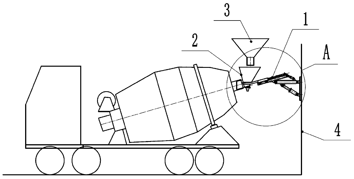
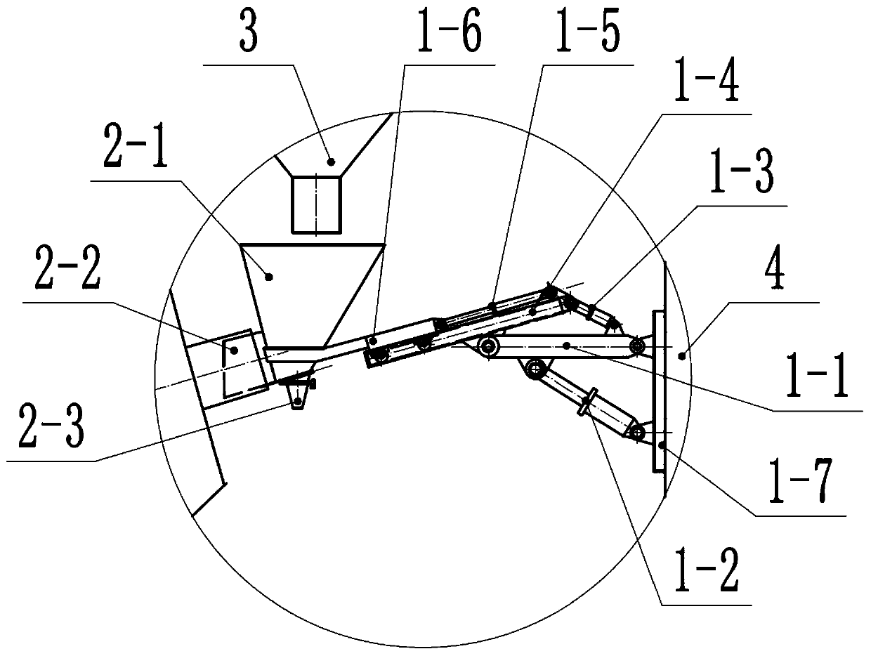
[0037] Such as figure 1 with 2 , in this embodiment, the robotic arm 1 is installed on the upright building 4 .
[0038] The mechanical arm 1 includes a base 1-7, a main arm 1-1, a swing arm 1-4, a first telescopic cylinder 1-2, a second telescopic cylinder 1-3, a third telescopic cylinder 1-5 and a support 1- 6.
[0039] The base 1-7 is fixedly installed on the upright building body 4 .
[0040] The rear end of the main arm 1-1 is rotatably connected to the front side of the base 1-7; the upper end of the first telescopic cylinder 1-2 is rotatably connected to the main arm 1-1, and the lower end is rotatably connected to the base 1-7. 7 Rotation connection, used to drive the main arm 1-1 to pitch and rotate relative to the base 1-7.
[0041] The swing arm 1-4 is mounted on the front end of the main arm 1-1 through rotation; one end of the second telescopic cylinder 1-3 is rotationally connected to the swing arm 1-4, and the other end is rotationally connected to the main ...
Embodiment 2
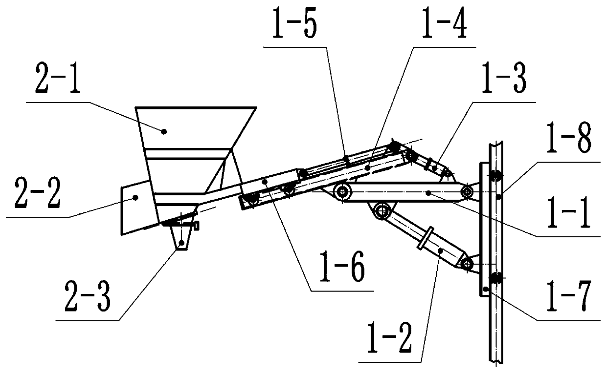
[0048] Such as image 3 , the difference between this embodiment and Embodiment 1 is:
[0049] The base 1-7 is installed on the upright building body 4 through vertically arranged slide rails 1-8 to realize lifting relative to the ground. The base 1-7 can be driven by a traction rope, a rack and pinion device or a lead screw and nut mechanism to realize lifting action.
[0050] Compared with the first embodiment, the adjustment space of the feeding hopper 2-1 and the launder 2-2 in the height direction is larger in this embodiment, which is convenient for adapting to mixer trucks of various heights.
Embodiment 3
[0052] The difference between this embodiment and embodiment one or two is: as Figure 4 (overlooking direction), the mechanical arm 1 also includes a fourth telescopic cylinder 1-9, one end of the fourth telescopic cylinder 1-9 is rotatably connected to the main arm 1-1, and the other end is rotatably connected to the base 1-7 , so as to drive the main arm 1-1 to swing horizontally relative to the base 1-7. At this time, other parts refer to figure 2 with image 3 , the rear end of the main arm 1-1, the rear end of the fourth telescopic cylinder 1-9 and the rear end of the first telescopic cylinder 1-2 are ball hinged. The first telescopic cylinder 1-2 is located directly below the main arm 1-1, and the fourth telescopic cylinder 1-9 is located in the same plane as the main arm 1-1.
[0053] The horizontal swing of the main arm 1-1 can also be driven by other mechanisms instead of the fourth telescopic cylinder 1-9, such as a motor gear mechanism and the like. The horizo...
PUM
 Abstract
Description
Claims
Application Information
 - R&D
- Intellectual Property
- Life Sciences
- Materials
- Tech Scout
- Unparalleled Data Quality
- Higher Quality Content
- 60% Fewer Hallucinations
Browse by: Latest US Patents, China's latest patents, Technical Efficacy Thesaurus, Application Domain, Technology Topic, Popular Technical Reports.
© 2025 PatSnap. All rights reserved.Legal|Privacy policy|Modern Slavery Act Transparency Statement|Sitemap|About US| Contact US: help@patsnap.com


