
A semi-automatic film sticking device

A film sticking device and semi-automatic technology, applied in the field of film sticking equipment preparation, can solve the problems of difficult to greatly reduce film sticking cost, low film sticking efficiency, inaccurate film sticking position, etc., so as to improve the scope of application and practicability, reduce film sticking cost, and improve film sticking. effect of speed

Active Publication Date: 2020-03-24
GUANGDONG BEIBEI ROBOT
View PDF1 Cites 0 Cited by
  • Summary
  • Abstract
  • Description
  • Claims
  • Application Information

AI Technical Summary

Problems solved by technology

[0002] After the molding of plastic products is completed, some appearance surfaces have relatively high quality requirements. In order to prevent the appearance surface of plastic products from being scratched or dirty, it is usually necessary to stick a protective film on the appearance surface of such plastic products. However, the existing The method of pasting protective film on the surface of plastic products is usually done by hand, which not only has low efficiency of film pasting, but also requires high cost of film pasting. At the same time, this manual film pasting method: (1) It is easy for staff to appear The position of the film is not accurate, it is necessary to tear off the protective film that has been pasted, and then re-apply the protective film. The torn protective film can only be wasted; It is easy to leave fingerprints on the appearance of plastic products, which affects the appearance; (3) Artificial film is easy to cause air bubbles between the film product and the protective film, which is difficult to eliminate, affecting the effect of the film and the practicability of the product
[0003] In response to these problems, some businesses have proposed a plastic product film sticking device (patent number: 201710948689.4). Since the device does not have a film cutting mechanism, it means that after the film sticking is completed, each plastic part has to be separated manually. The cost is high, so it is still difficult to greatly reduce the cost of the film

Method used


Image

  • A semi-automatic film sticking device
  • A semi-automatic film sticking device
  • A semi-automatic film sticking device

Examples


Embodiment Construction

[0024] The structural principle and working principle of the present invention will be further described in detail below in conjunction with the accompanying drawings.

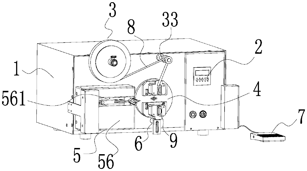
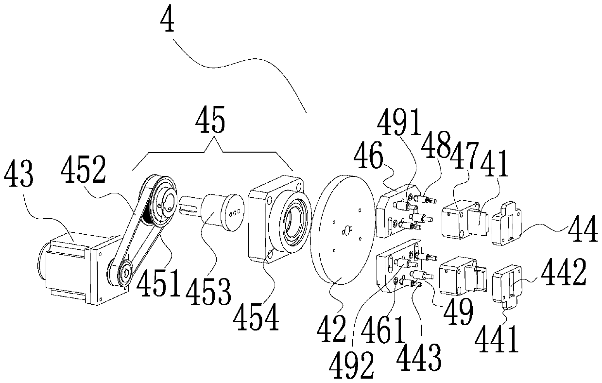
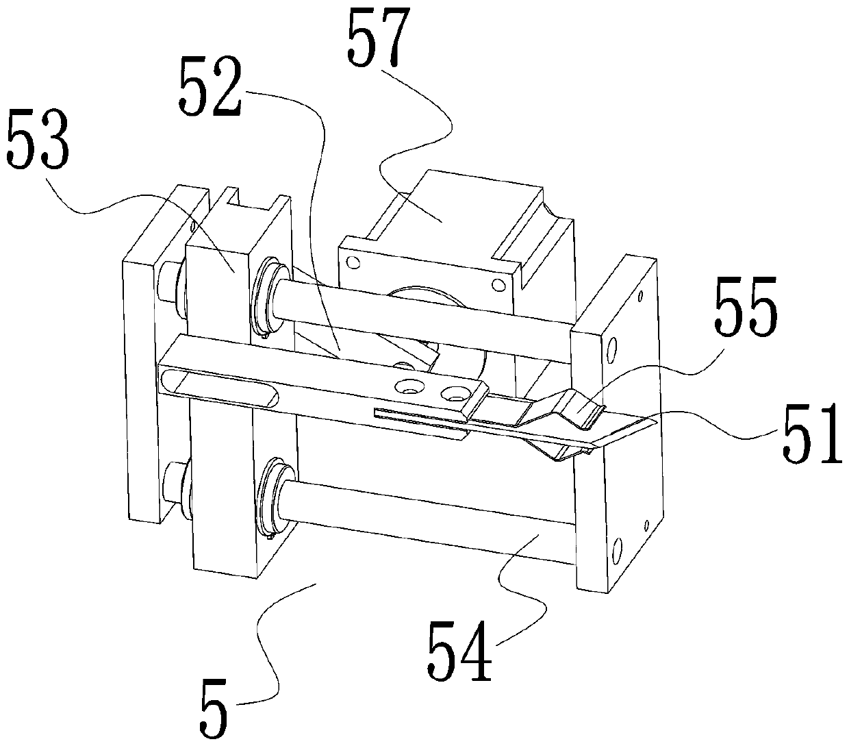
[0025] Such as figure 1 As shown, a semi-automatic film sticking device includes a casing 1 and a foot switch 7, the casing 1 is provided with a control box 2, a film supply mechanism 3, a film sticking mechanism 4, a film cutting mechanism 5 and an ejection mechanism 6, The film feeding mechanism 3 is wound with a film tape 8, and the film tape 8 enters the film pasting mechanism 4 from the side of the film pasting mechanism 4 close to the film supply mechanism 3, and is attached to a side of the workpiece 9. The film pasting mechanism 4 includes a fixed mount 41 for fixing the workpiece 9, a turntable 42 that drives the fixed mount 41 to rotate and stick a film on the surface of the workpiece 9, and a first drive motor 43 that drives the turntable 42 to rotate. There are two fixed mounts 41, which are respec...


PUM


Abstract

The invention discloses a semiautomatic film laminating device. The semiautomatic film laminating device comprises a machine casing, wherein a control box, a film supply mechanism, a film laminating mechanism, a film cutting mechanism and an ejection mechanism are arranged on the machine casing; a film belt is wound on the film supply mechanism, is sent into the film laminating mechanism from oneside, near the film supply mechanism, of the film laminating mechanism, and is laminated to one side of a workpiece; the film laminating mechanism comprises two fixed frames, a rotary disc and a firstdrive motor, the two fixed frames are respectively fixedly arranged at the upper end and lower end of the rotary disc, an ejection disc is arranged behind each fixed frame, and a convex block is arranged on each ejection disc; the film cutting mechanism comprises a film cutting knife and a second drive motor; the ejection mechanism comprises an infrared sensor, an ejection block and a drive air cylinder; the infrared sensor is arranged on the ejection block; the first drive motor, the second drive motor, the drive air cylinder and the infrared sensor are respectively electrically connected with the control box. The semiautomatic film laminating device has the advantages that the semiautomatic film laminating and film cutting procedures are realized, the film laminating efficiency is improved, and the film laminating cost is reduced.

Description

technical field [0001] The invention relates to the technical field of film sticking equipment preparation, in particular to a semi-automatic film sticking device. Background technique [0002] After the molding of plastic products is completed, some appearance surfaces have relatively high quality requirements. In order to prevent the appearance surface of plastic products from being scratched or dirty, it is usually necessary to stick a protective film on the appearance surface of such plastic products. However, the existing The method of pasting protective film on the surface of plastic products is usually done by hand, which not only has low efficiency of film pasting, but also requires high cost of film pasting. At the same time, this manual film pasting method: (1) It is easy for staff to appear The position of the film is not accurate, it is necessary to tear off the protective film that has been pasted, and then re-apply the protective film. The torn protective film ...

Claims


Application Information

Patent Timeline
Patent Type & Authority Patents(China)
IPC IPC(8): B29C63/02
CPCB29C63/02
Inventor 向贞一张开浪
Owner GUANGDONG BEIBEI ROBOT
Learn More