An explosion-proof exterior wall with pressure relief function

A functional and external wall technology, applied in the direction of walls, ventilation systems, heating methods, etc., can solve the problems of secondary injury to personnel, poor sealing effect of shutters, and rapid diffusion of unprofitable high-pressure air waves. Improve the effect of anti-knock and pressure relief effect

Active Publication Date: 2019-11-29
CHANGAN UNIV
View PDF6 Cites 0 Cited by
  • Summary
  • Abstract
  • Description
  • Claims
  • Application Information

AI Technical Summary

Problems solved by technology

[0002] Building explosion-proof is an explosion-proof design for buildings with explosion hazards such as factories and warehouses. At present, buildings with explosion hazards should be single-story. A large amount of gas and heat are released, which creates a high pressure in the room. In order to prevent the load-bearing components of the building from being damaged due to the strong explosive force, the usual method is to design the top of the explosion-proof wall as a weak pressure relief structure. The current common way to design the pressure relief structure is to install the corresponding skylight, but when the skylight explodes, a large amount of glass shards will splash and cause secondary damage to personnel. In order to solve this problem, a kind of The explosion-proof wall using louvers as the pressure relief structure, although the pressure relief structure of the explosion-proof wall can effectively avoid the secondary damage caused by the splashing glass fragments, but the air waves generated at the moment of the explosion spread in a straight line. The blades of the louvers are designed to be inclined, which is not conducive to the rapid diffusion of high-pressure air waves. At the same time, the overall sealing effect of the louvers is poor. For some dangerous goods that are prone to moisture and explosion, the storage environment is very dangerous.

Method used


Image

  • An explosion-proof exterior wall with pressure relief function

Examples


Embodiment Construction

[0011] In order to make the technical means, creative features, goals and effects achieved by the present invention easy to understand, the technical solutions in the embodiments of the present invention will be clearly and completely described below in conjunction with the accompanying drawings in the embodiments of the present invention.

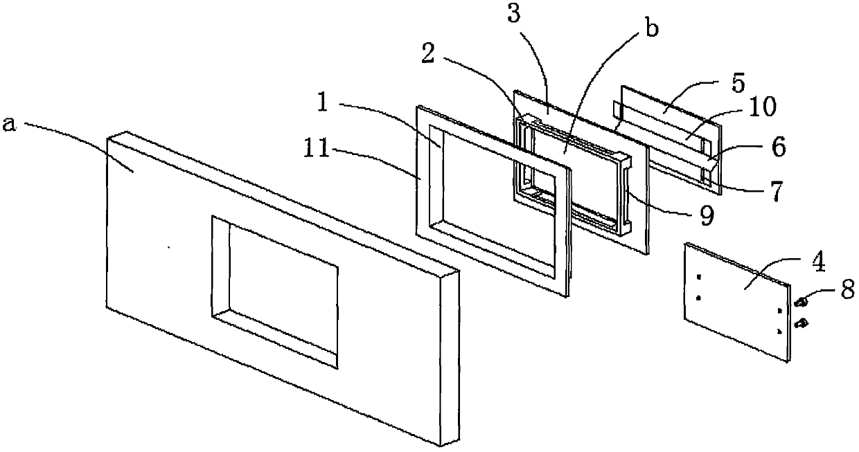
[0012] see figure 1 , this specific embodiment is realized by adopting the following technical scheme, which includes a ventilation pipe 1 located in the explosion-proof wall a, the interior of the ventilation pipe 1 is provided with a pressure relief pipe 2, and the outer surface of the pressure relief pipe 2 is in contact with There is a cavity for high-pressure air waves to pass between the inner walls of the ventilation pipe 1, and the end of the pressure relief pipe 2 is welded vertically on the baffle 3, and the end of the pressure relief pipe 2 opposite to the baffle 3 A positioning plate 4 is welded and fixed, and the baffle plate ...


PUM


Abstract

The invention discloses an explosion-proof outer wall with a pressure relief function, which comprises a ventilation pipe (1) located in the explosion-proof wall body (a), and a pressure relief pipe (2) is arranged inside the ventilation pipe (1). A cavity for high-pressure air waves to pass is left between the outer surface of the pressure relief pipe (2) and the inner wall of the ventilation pipe (1), and the end of the pressure relief pipe (2) is vertically welded on the baffle ( 3), a positioning plate (4) is welded and fixed at the end of the pressure relief pipe (2) opposite to the baffle (3), and the baffle (3) is provided with a pressure relief hole (b) in the middle as a whole A plate-shaped structure, the inside of the pressure relief hole (b) is provided with a pressure relief plate (5) in clearance fit with it. The invention is simple in structure and easy to use, and can effectively improve the anti-explosion and pressure relief effects of the whole wall body while ensuring the sealing effect.

Description

technical field [0001] The invention relates to the technical field related to explosion-proof buildings, in particular to an explosion-proof outer wall with a pressure relief function. Background technique [0002] Building explosion-proof is an explosion-proof design for buildings with explosion hazards such as factories and warehouses. At present, buildings with explosion hazards should be single-story. A large amount of gas and heat are released, which creates a high pressure in the room. In order to prevent the load-bearing components of the building from being damaged due to the strong explosive force, the usual method is to design the top of the explosion-proof wall as a weak pressure relief structure. The current common way to design the pressure relief structure is to install the corresponding skylight, but when the skylight explodes, a large amount of glass shards will splash and cause secondary damage to personnel. In order to solve this problem, a kind of The ex...

Claims


Application Information

Patent Timeline
Patent Type & Authority Patents(China)
IPC IPC(8): E04B2/00E04B1/92F24F7/10
CPCE04B1/92E04B2/00F24F7/10
Inventor 孙珊珊
Owner CHANGAN UNIV
Why Eureka
Try Eureka