Device carrier for lamps

A carrier and installation area technology, applied in the field of light engines, can solve problems such as LED circuit board replacement cannot be performed smoothly, and achieve the effect of reducing land occupation requirements and simplifying installation

Active Publication Date: 2021-08-24
ZUMTOBEL LIGHTING INC
View PDF2 Cites 0 Cited by
  • Summary
  • Abstract
  • Description
  • Claims
  • Application Information

AI Technical Summary

Problems solved by technology

However, in contrast to the aforementioned classic light sources, the replacement of the individual LED circuit boards generally cannot be carried out smoothly, since it is usually stipulated that the LED circuit board is mounted on a so-called device carrier, which then forms a structural unit together with the circuit board housed in a lamp

Method used


Image

  • Device carrier for lamps
  • Device carrier for lamps
  • Device carrier for lamps

Examples


Embodiment Construction

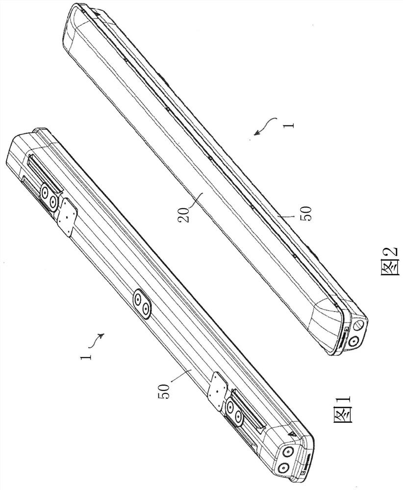
[0037] exist figure 1 with figure 21 firstly shows two perspective views of a damp-proof lamp generally designated with the reference number 1, ie the damp-proof lamp is intended to be used in particular in areas where in particular higher air humidity can also be present. In particular, the lamp 1 should be designed in such a way that the penetration of dust and / or moisture into the inner region of the lamp 1 is prevented. The lamp 1 should then meet the requirements of the protection class IP65, ideally IP66, by means of the sealing measures which will be described in more detail below.

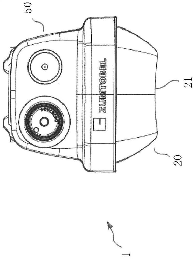
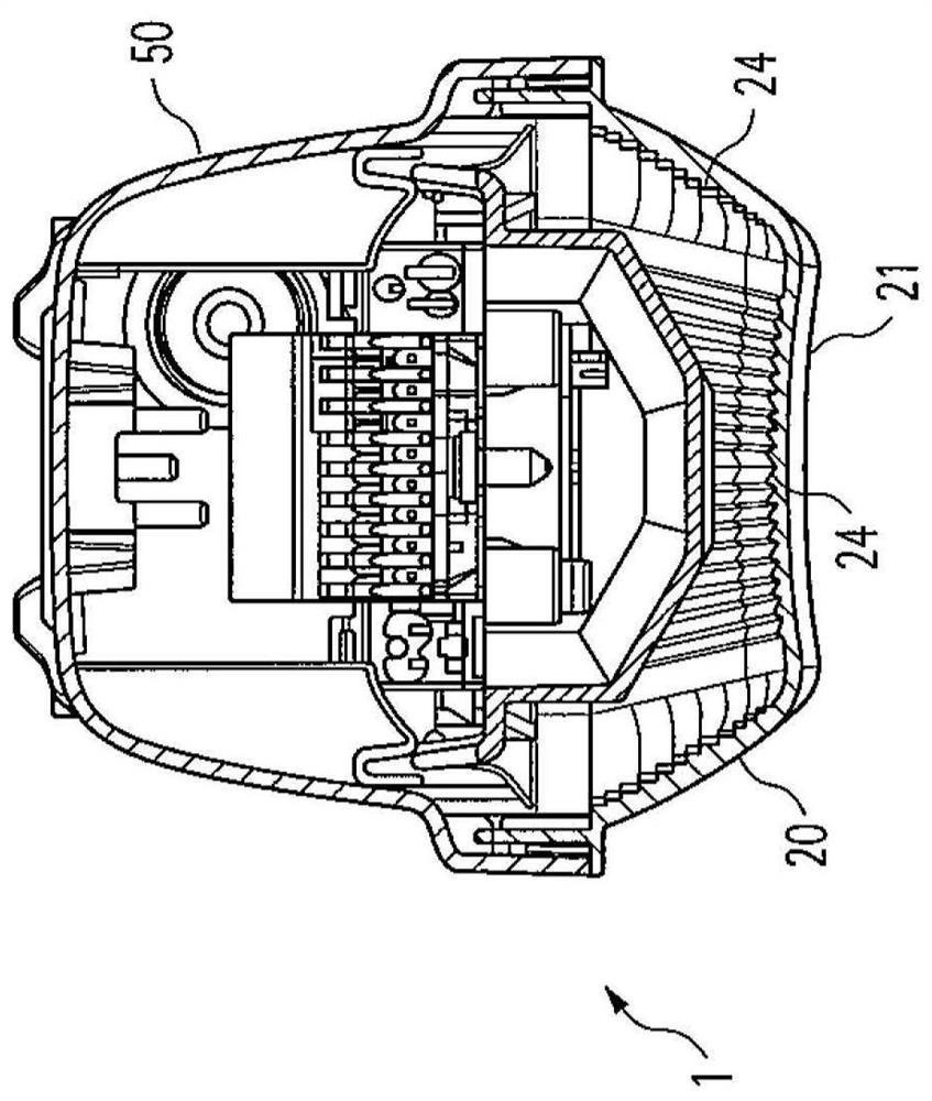
[0038] The main parts of the lamp 1 are the so-called lamp box groove 50, the cover 20 and the following will be described in detail but in figure 1 with figure 2 The device carrier, which cannot be seen in the figure, is accommodated in the space enclosed by the lamp box slot 50 and the cover 20 and houses the components responsible for the light emission. That is, the lamp housing i...


PUM


Abstract

The invention relates to a device carrier for a lamp. The device carrier (100) for the lamp (1) is formed from a sheet metal part with a plate-like section (101) through which two opposing mounting areas are formed, wherein the two mounting The first installation area in the area is configured for arranging the light-emitting element unit, especially for arranging the LED circuit board (130), and the second installation area opposite to the first installation area is configured for arranging at least one LED circuit board (130) for the light-emitting element unit. The powered drivers (140,141). The plate-shaped section (101) has a plurality of spacers (110) formed in one piece, which protrude from the plane of the plate-shaped section (101) into one of the two mounting regions and form a A raised support surface (111) for the light unit or the driver (140, 141).

Description

technical field [0001] The invention relates to a device carrier for a lamp, which is provided for supporting a light unit and is provided with a driver for supplying the light unit. The invention also relates to a so-called light engine to be used in a lamp. Background technique [0002] A light engine generally refers to a lamp structural unit which is responsible for the generation of the light emitted by the lamp. That is to say, the structural unit especially primarily contains the illuminants required for the actual illuminance, but possibly also additional components responsible for supplying the illuminants. Usually, the luminous element is also assigned a so-called primary optic, which performs the first influence on the light generated by the luminous element. [0003] Although in the early days as illuminants, for example, incandescent bulbs or fluorescent lamps were used, which can be easily replaced by the user in the event of a fault, semiconductor-based illu...

Claims


Application Information

Patent Timeline
Patent Type & Authority Patents(China)
IPC IPC(8): F21S8/00F21V21/00F21V23/00F21Y115/10
CPCF21V29/15F21V19/003F21V19/0055F21V23/001F21V23/005F21V23/026F21Y2115/00F21S8/00F21V21/00F21V23/003F21Y2115/10F21Y2103/10
Inventor W·巴赫特M·斯皮格尔C·恩德
Owner ZUMTOBEL LIGHTING INC
Why Eureka
Try Eureka