Power utilization inspection device
A technology of electricity inspection and current detection module, applied in the direction of measuring device, measuring device casing, measuring electricity, etc., can solve the problems of inconvenient use and site environment restrictions, and achieve the improvement of measurement height, not limited by site environment, and convenient effect used
Pending Publication Date: 2018-09-07
GUANGDONG POWER GRID CO LTD +1
View PDF5 Cites 1 Cited by
- Summary
- Abstract
- Description
- Claims
- Application Information
AI Technical Summary
Problems solved by technology
[0004] In order to overcome the disadvantages of being restricted by the site environment and being inconvenient to use described in the prior art, the present invention provides an electrical inspection device, which is not restricted by the site environment and is more convenient to use
Method used
View moreImage
Smart ImageViewing Examples
Examples
Embodiment 1
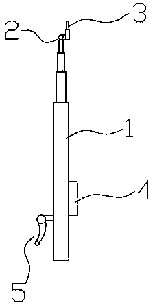
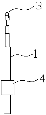
[0027] An electrical inspection device, comprising a telescopic insulating rod 1, a detection module 3 arranged at the upper end of the telescopic insulating rod 1, and a display terminal 4 arranged at the lower part of the telescopic insulating rod 1, the extension height of the telescopic insulating rod 1 is 4 to 6 m, The detection module 3 and the display terminal 4 are connected by bluetooth;
Login to View More PUM
 Abstract
The invention discloses a power utilization inspection device which includes a telescopic insulating rod, a detecting module disposed on the upper portion of the telescopic insulating rod and a display terminal disposed on the lower portion of the telescopic insulating rod. The detecting module is in communication connection with the display terminal. A universal joint is arranged between the detecting module and the telescopic insulating rod. The detecting module includes a clamp type current detecting module, and the lower portion of the telescopic insulating rod is provided with a clamp type measurement operation handle for operating the clamp type current detecting module. According to the power utilization inspection device, the universal joint and the telescopic insulating rod are adopted. The detecting module is adjusted through the universal joint to achieve a proper posture, and the measuring height is raised by the telescopic insulating rod. The power utilization inspection device has the advantages of being not restricted by the site environment and being convenient to use.
Description
technical field [0001] The invention relates to the field of power supply, and more specifically, to an electricity checking device. Background technique [0002] In the inspection of electricity consumption, the main tools for anti-stealing electricity and investigating and dealing with power violations are current clamp ammeters, electroscope pens, on-site calibration protocols, phase voltammeters and other tools, but due to the limitations of the site environment, it is difficult to obtain evidence. And other issues. The current instrumentation is mainly operated on the ground, but due to environmental reasons in actual use, it is far from meeting the needs of the work. [0003] Therefore, it is necessary to design an electrical inspection tool that is not restricted by the site environment and is more convenient to use. Contents of the invention [0004] In order to overcome the drawbacks of the above-mentioned prior art, which are limited by the site environment and...
Claims
Login to View More Application Information
Patent Timeline
 Patent Type & Authority Applications(China)
IPC IPC(8): G01R31/00G01R31/02G01R19/00G01R19/145G01R1/04
CPCG01R1/04G01R19/0084G01R19/145G01R31/00G01R31/50
Inventor 欧阳书远
Owner GUANGDONG POWER GRID CO LTD
Features
- R&D
- Intellectual Property
- Life Sciences
- Materials
- Tech Scout
- Unparalleled Data Quality
- Higher Quality Content
- 60% Fewer Hallucinations
Learn More Browse by: Latest US Patents, China's latest patents, Technical Efficacy Thesaurus, Application Domain, Technology Topic, Popular Technical Reports.
© 2025 PatSnap. All rights reserved.Legal|Privacy policy|Modern Slavery Act Transparency Statement|Sitemap|About US| Contact US: help@patsnap.com


