Eureka AIR delivers breakthrough ideas for toughest innovation challenges, trusted by R&D personnel around the world.

Ignition signal wake-up loop for motor controller and control method

A motor controller, ignition signal technology, applied in control drive, general control system, electrical testing/monitoring, etc., can solve problems such as increased hardware cost, inability to use parts and components, and inability to implement circuit design solutions to improve functional safety level, effect of preventing interference

Active Publication Date: 2018-09-07
HEFEI JUYI POWER SYST CO LTD
View PDF8 Cites 2 Cited by
  • Summary
  • Abstract
  • Description
  • Claims
  • Application Information

AI Technical Summary

Problems solved by technology

[0003] (1) The wake-up signal loop is considered from the perspective of the vehicle system, and the wake-up signal loop is not explained from the perspective of components, and how the component motor controller cooperates with the vehicle to monitor the wake-up state to improve the safety performance of the vehicle;
[0004] (2) More components are used, which increases the hardware cost;
[0005] (3) It is unlikely that it can be used as a reference, and it cannot be used in parts;
[0006] (4) Mainly the layout of the electrical system forms a wake-up loop and cannot realize the circuit design scheme
[0010] The patent considers the wake-up of the ignition signal from the perspective of the whole vehicle, and does not introduce how to distinguish between the two wake-up methods, and how different wake-up modes work, and does not describe how the parts work with the whole vehicle.

Method used


Image

  • Ignition signal wake-up loop for motor controller and control method
  • Ignition signal wake-up loop for motor controller and control method

Examples


Embodiment Construction

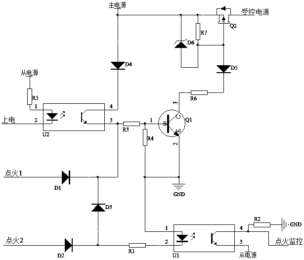
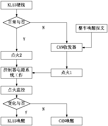
[0031] The present invention proposes an ignition signal wake-up loop for a motor controller. Using this scheme can satisfy the redundant design of functional safety, and can distinguish two wake-up modes at the same time. The principle is as follows: figure 1 As shown, it includes three working states.

[0032] (1) KL15 hard-wire wake-up working status:

[0033] When the ignition coil of the whole vehicle starts to work, the KL15 ignition signal is generated, and the high-level signal passes through the ignition 2, that is, the KL15 ignition terminal turns on the diodes D2 and D3. Then it reaches the base of the transistor Q1 through the resistor R3, turns on the transistor Q1, pulls the gate of the P-type MOS transistor Q2 to the ground, Q2 is turned on, the 12V power supply system (controlled power supply) of the controller starts to work, and wakes up the controller (where D6 is the zener diode used to protect the gate-source of Q2, R7 is the pull-down resistor for the ga...


PUM


Abstract

The invention discloses an ignition signal wake-up loop for a motor controller and a control method. The loop includes a KL15 ignition end and a CAN ignition end. The two ignition ends are connected to a base of a transistor Q1 through diodes D2 and D1 respectively, and a collector of the transistor Q1 is connected with a grid of a P-type MOS transistor Q2 sequentially through a resistor R6 and adiode D5 which are in series connection, a source and a drain of the MOS transistor Q2 are connected with a main power supply and a controlled power supply respectively, and when the MOS transistor Q2is connected, the controlled power supply of a controller starts to operate, to achieve the purpose of waking up the controller. An optocoupler U1 primary is connected through an ignition 2, a 4-pinignition of the optocoupler U1 monitors changes of level, and an MCU detects the changes and then controls the level of a pin 2 of U2; at the same time pins 3 and 4 of the U2 are connected, and the MCU in the controller can monitor a KL15 rigid line wake-up signal in real time. According to the ignition signal wake-up loop for the motor controller and the control method, a related CAN message wake-up mode is added and serves as a redundant design of the KL15 rigid line wake-up wake-up mode, ensuring that the controller can respond to the requirements of a complete vehicle in real time.

Description

technical field [0001] The invention relates to new energy vehicles, in particular to an ignition signal wake-up loop of a motor controller and a control method. Background technique [0002] Existing new energy vehicles often encounter abnormalities in the wiring harness between the vehicle and the motor controller, especially when the KL15 hard wire is broken, and the relevant wake-up signal generated by the ignition coil of the vehicle cannot wake up the controller. The wake-up schemes of the prior art have the following disadvantages: [0003] (1) The wake-up signal loop is considered from the perspective of the vehicle system, and the wake-up signal loop is not explained from the perspective of components, and how the component motor controller cooperates with the vehicle to monitor the wake-up state to improve the safety performance of the vehicle; [0004] (2) More components are used, which increases the hardware cost; [0005] (3) It is unlikely that it can be use...

Claims


Application Information

Patent Timeline
IPC IPC(8): G05B23/02B60L15/00
CPCB60L15/00G05B23/0213
Inventor 刘蕾许建豪胡宗滔苑红伟刘忠良
Owner HEFEI JUYI POWER SYST CO LTD
Why Eureka
Eureka Blog
Learn More