
Battery pack structure

A technology of battery packs and battery modules, applied in secondary batteries, circuits, electrical components, etc., can solve the problems of high cost, poor heat dissipation effect, heavy weight, etc., and achieve less space occupation, good heat dissipation effect, and simple structure Effect

Pending Publication Date: 2018-09-07
OPTIMUM BATTERY CO LTD
View PDF0 Cites 0 Cited by
  • Summary
  • Abstract
  • Description
  • Claims
  • Application Information

AI Technical Summary

Problems solved by technology

Therefore, in order to shorten the charging time of electric vehicles and increase the charging rate of battery packs of electric vehicles, high-rate charging often leads to a sharp rise in the internal temperature of the battery pack, which in turn affects the safety of the entire electric vehicle.
However, the heat dissipation methods of the existing battery packs have the following problems: 1. Air-cooled heat dissipation is adopted. Although the air-cooled heat dissipation is low in cost, the heat dissipation effect is poor; 2. Although the liquid cooling heat dissipation effect is good, the structure is more complicated, the cost is high, and the weight is high. big, low security

Method used


Image

  • Battery pack structure
  • Battery pack structure
  • Battery pack structure

Examples


Embodiment Construction

[0014] In order to make the object, technical solution and beneficial technical effects of the present invention clearer, the present invention will be further described in detail below in conjunction with the accompanying drawings and specific embodiments. It should be understood that the specific implementations described in this specification are only for explaining the present invention, not for limiting the present invention.

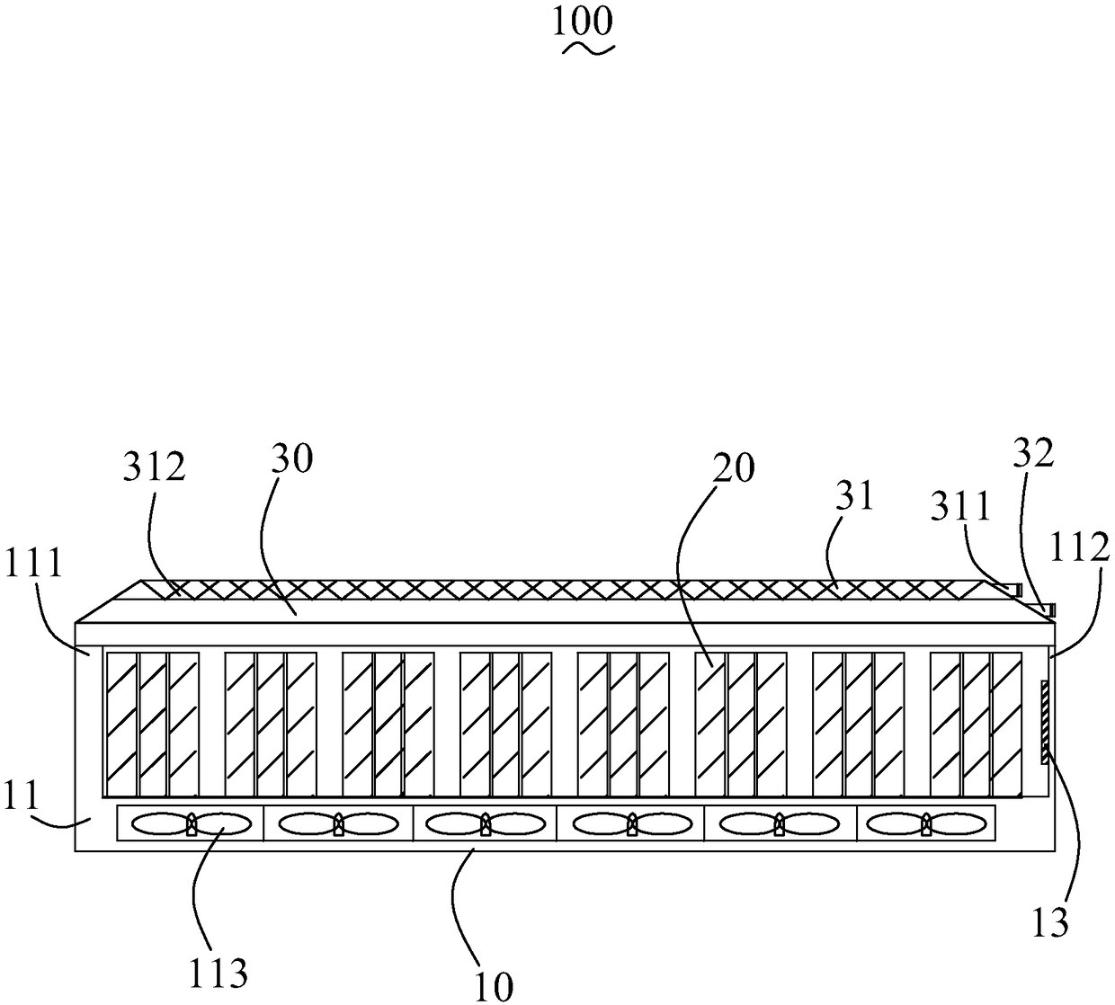
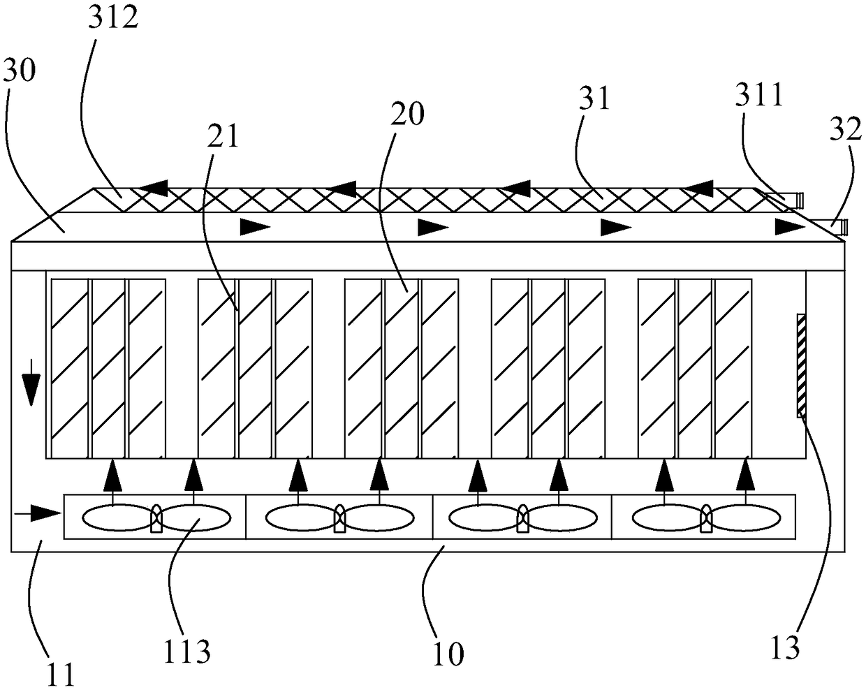
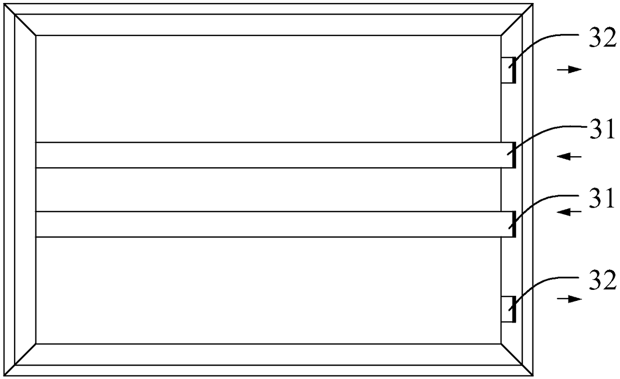
[0015] see Figure 1 to Figure 4 , the present invention provides a battery pack structure 100 , comprising a box body 10 having an open end and a hollow cuboid shape, a plurality of battery modules 20 and a box cover 30 corresponding to the box body 10 . The box body 10 is integrally formed and has a flow channel 11 on its inner wall. The flow channel 11 includes an open end 111 and a closed end 112 away from the open end 111 . Each battery module 20 is provided with a plurality of cooling passages 21 that run through both ends of the battery mod...


PUM


Abstract

The utility model relates to a battery pack structure comprising a box body, a plurality of battery modules and a box cover; the inner wall of the box body is provided with a flow channel, wherein theflow channel comprises an open end and a closed end; each battery module is provided with a plurality of heat dissipation channels penetrating the two ends of the battery modules, a plurality of spaced-apart pipes are embedded in the box cover, each pipe includes an air intake end exposed outside the box cover and an air outlet end buried inside the box cover and away from the air inlet end, thebox cover is further provided with a plurality of spaced-apart exhaust ports away from the air outlet end, and the plurality of exhaust ports are located on the two sides of the plurality of pipes; the plurality of battery modules are packed in the box body, the ends, adjacent to the bottom of the box body, of the heat dissipation channels of each of the battery modules are communicated with the flow channel of the box body; the box cover covers the open end of the box body, the air outlet end of the pipe is communicated with the opening end of the flow channel of the box body, and the exhaustports of the box cover are communicated with the ends, near the box cover, of the plurality of heat dissipation passages of each battery module.

Description

【Technical field】 [0001] The invention relates to the technical field of batteries, in particular to a battery pack structure. 【Background technique】 [0002] With the development of the electric vehicle industry, people's requirements for all aspects of electric vehicles are gradually increasing, especially the charging efficiency of electric vehicles. Therefore, in order to shorten the charging time of electric vehicles and increase the charging rate of battery packs of electric vehicles, high-rate charging often leads to a sharp rise in the internal temperature of the battery pack, which in turn affects the safety of the entire electric vehicle. However, the heat dissipation methods of the existing battery packs have the following problems: 1. Air-cooled heat dissipation is adopted. Although the air-cooled heat dissipation is low in cost, the heat dissipation effect is poor; 2. Although the liquid cooling heat dissipation effect is good, the structure is more complicated,...

Claims


Application Information

Patent Timeline
Patent Type & Authority Applications(China)
IPC IPC(8): H01M10/613H01M10/625H01M10/663H01M10/6557H01M10/6563H01M10/6556H01M10/637
CPCH01M10/613H01M10/625H01M10/637H01M10/6556H01M10/6557H01M10/6563H01M10/663Y02E60/10
Inventor 黄龙超吴施荣许浩饶睦敏李金林
Owner OPTIMUM BATTERY CO LTD
Learn More