
Chain joint dismounting machine

A technology of chain and joint dismantling, which is applied in the direction of belts/chains/gears, chain elements, mechanical equipment, etc. It can solve the problems of manual sorting, time-consuming and laborious, etc., and achieve the goal of avoiding sorting, improving production efficiency, and high degree of automation Effect

Active Publication Date: 2018-09-11
浙江东亿自动化科技有限公司
View PDF6 Cites 4 Cited by
  • Summary
  • Abstract
  • Description
  • Claims
  • Application Information

AI Technical Summary

Problems solved by technology

However, after the chain is dismantled, the chain pins and chain pieces are collected in a waste box by this joint dismantling machine, and manual sorting is required for subsequent recycling, which is time-consuming and laborious

Method used


Image

  • Chain joint dismounting machine
  • Chain joint dismounting machine
  • Chain joint dismounting machine

Examples


Embodiment 1

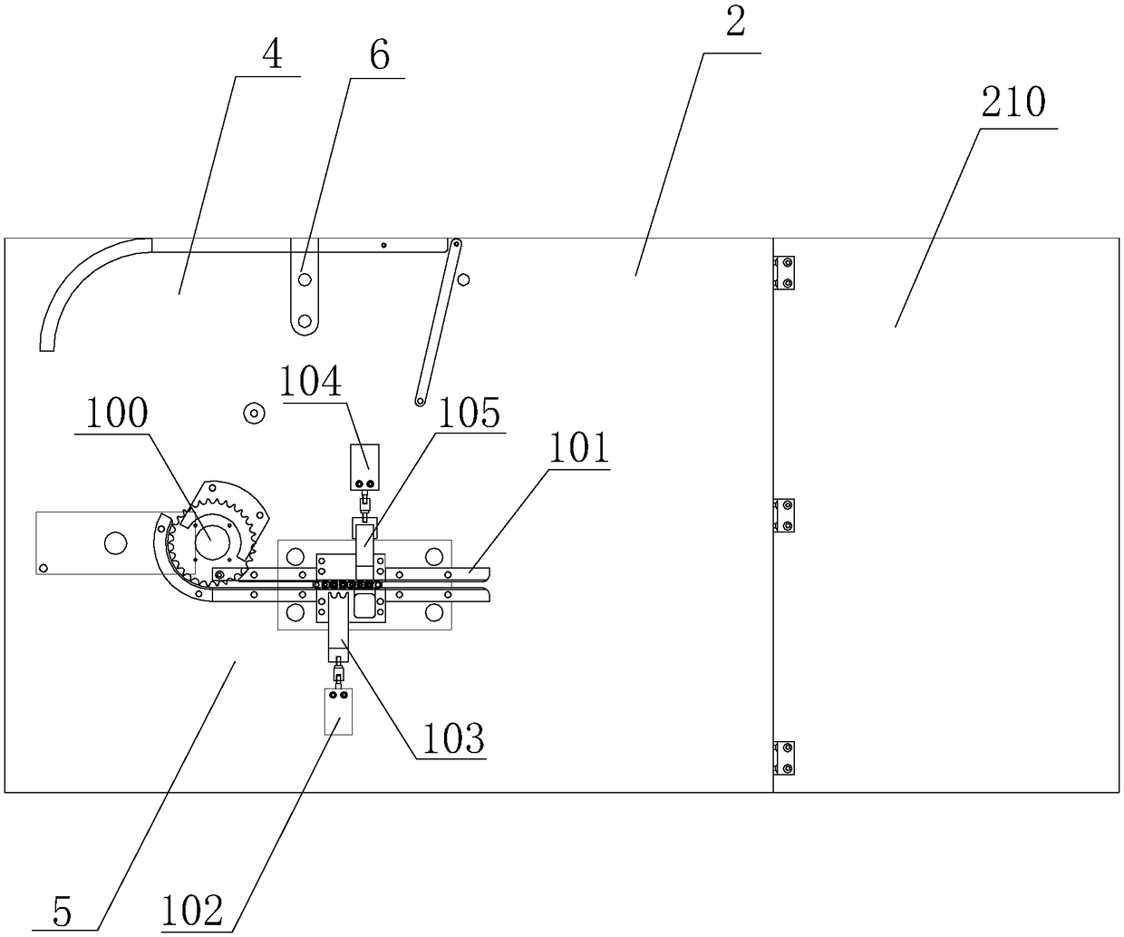
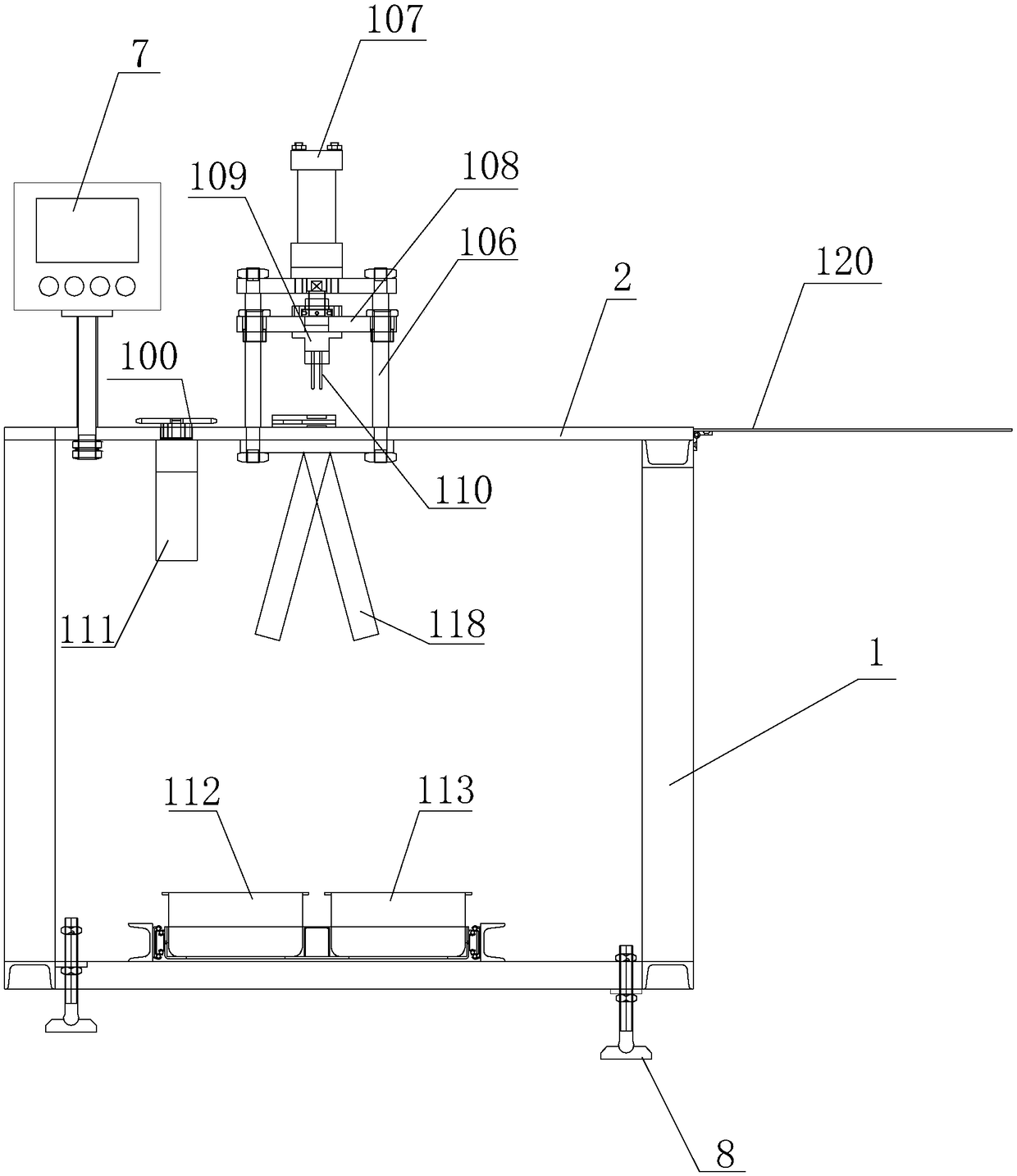
[0029] Such as figure 1 , figure 2 As shown, a chain splitting machine includes a frame 1, a table 2 and a splitting mechanism. The bottom of the frame is provided with a height-adjustable machine foot 8, and the table top is arranged on the frame; the table top is divided into a stacking chain area 4 and a disassembly area 5 according to the process steps; the table top is located after the chain is dismantled. One side of the output is a foldable discharge flap 120 . The PLC controller 7 that controls the circuit of the whole device is provided on the table.

[0030] Such as figure 1 As shown, the chain stacking area is provided with a position sensor 6 and a rotatable chain retaining plate 116, and a detachable positioning post 117 is provided on the outside of the chain retaining plate on the table.

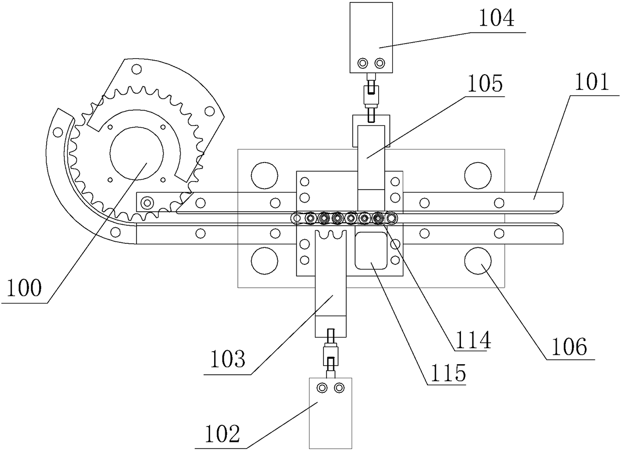
[0031] Such as image 3 , Figure 4 As shown, the joint removal mechanism includes several sprockets 100 located in the joint removal area, a chain guide channel 101, ...

Embodiment 2

[0034] The difference between this embodiment and embodiment 1 is that Figure 5 As shown, in this embodiment, the steel needle is provided with a vertical buffer spring 119 in the slot on the joint seat.


PUM


Abstract

The invention relates to chain production equipment, and discloses a chain joint dismounting machine. The chain joint dismounting machine comprises a rack, a table top and a joint dismounting mechanism. The table top is divided into a chain stacking area and a joint dismounting area. The joint dismounting mechanism comprises a plurality of joints of chain wheels, a guide chain channel, a first aircylinder, a positioning tooth plate, a second air cylinder, a chain sheet push plate, a vertical rail, a joint dismounting oil cylinder, a sliding table, a joint dismounting base, steel needles, a servo motor, a chain shaft collecting box and a chain sheet collecting box. The first air cylinder and the second air cylinder drive the positioning tooth plate and the chain sheet push plate correspondingly. The vertical rail is erected above the positioning tooth plate and the chain sheet push plate. The joint dismounting oil cylinder is fixed to the top of the vertical rail, the sliding table isarranged on the vertical rail, the joint dismounting base is fixed to the sliding table, the two steel needles are arranged at the bottom of the joint dismounting base, and the steel needles are located over a shaft of the chain which is about to be subjected to joint dismounting. The chain shaft collecting box and the chain sheet collecting box are located below a chain shaft hole and a chain sheet hole correspondingly. The joint dismounting machine is high in automation degree, chain shafts and chain sheets, all of which are obtained after joint dismounting can be independently recycled, andthe production efficiency can be greatly improved.

Description

technical field [0001] The invention relates to the field of chain production equipment, in particular to a chain dismantling machine. Background technique [0002] The length of the chain is very long after production, so the chain needs to be disassembled according to the needs, and disassembled into small sections to make the length meet the demand. [0003] The Chinese patent with the application number CN201520035641.0 discloses a self-counting chain dismantling device, which includes a frame, a chain feeding mechanism, a chain positioning mechanism, a chain dismantling mechanism and a material leakage mechanism. The chain feeding mechanism includes a sprocket Start the proximity switch, chain guide rail, sprocket and servo motor. The chain positioning mechanism includes a positioning cylinder and a positioning block. One side of the positioning cylinder is also equipped with a positioning cylinder in-position proximity switch. The hydraulic cylinder is fixed above the...

Claims


Application Information

Patent Timeline
IPC IPC(8): B23P19/027F16G13/00
CPCB23P19/027F16G13/00
Inventor 章立芳
Owner 浙江东亿自动化科技有限公司
Learn More