
Release paper suction feeding and cutting applying device

A technology of applying device and release paper, which is applied in the direction of pile separation, sending objects, thin material processing, etc., can solve the problems of cutting width adjustment, inability to adjust the position of release paper, and cutter width, etc., and achieves stable and reliable cutting effect.

Inactive Publication Date: 2018-09-11
杭州军锋机械有限公司
View PDF0 Cites 4 Cited by
  • Summary
  • Abstract
  • Description
  • Claims
  • Application Information

AI Technical Summary

Problems solved by technology

[0002] Medical pads are often compounded with some release paper stickers on the side or in the middle. Therefore, it is necessary to add special release paper conveying and release paper cutting and applying (compositing or pasting) devices to the medical pad production line; currently, the conventional The release paper conveying mechanism transports the release paper from the release paper roll to the release paper cutting application mechanism for cutting and application, and the cutting length of the release paper is difficult to control; and the conventional release paper cutting application mechanism generally The width of the cutter is the same as the width of the cutter roller, and the cutting width cannot be adjusted. When the width of the release paper is much smaller than the width of the cutter and the cutter roller, the cutter will be too wide and the cutting force will be too scattered , the cutting of the release paper is not stable enough, and the position of the release paper on the main material is fixed and cannot be adjusted. Each product needs a specially designed release paper cutting application mechanism

Method used


Image

  • Release paper suction feeding and cutting applying device
  • Release paper suction feeding and cutting applying device
  • Release paper suction feeding and cutting applying device

Examples


Embodiment Construction

[0029] The present invention will be described in further detail below in conjunction with the accompanying drawings, but it is not intended to limit the protection scope of the present invention.

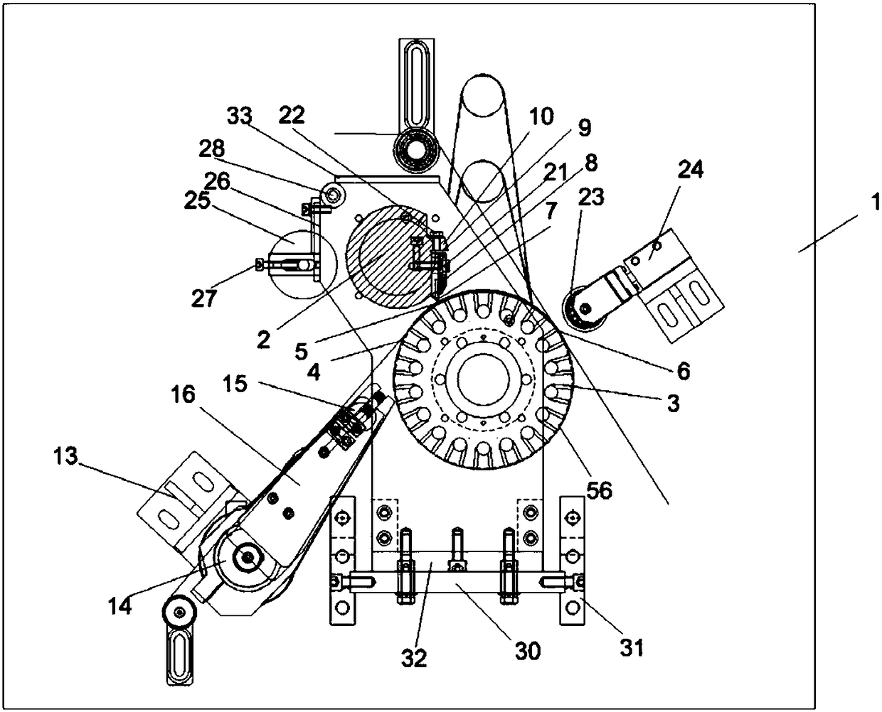
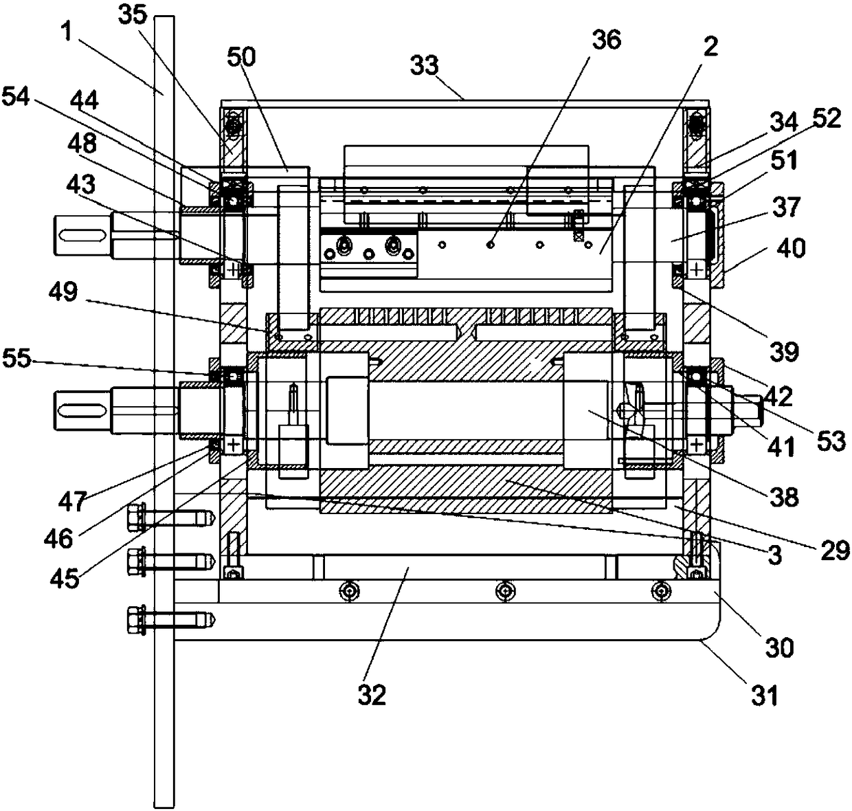
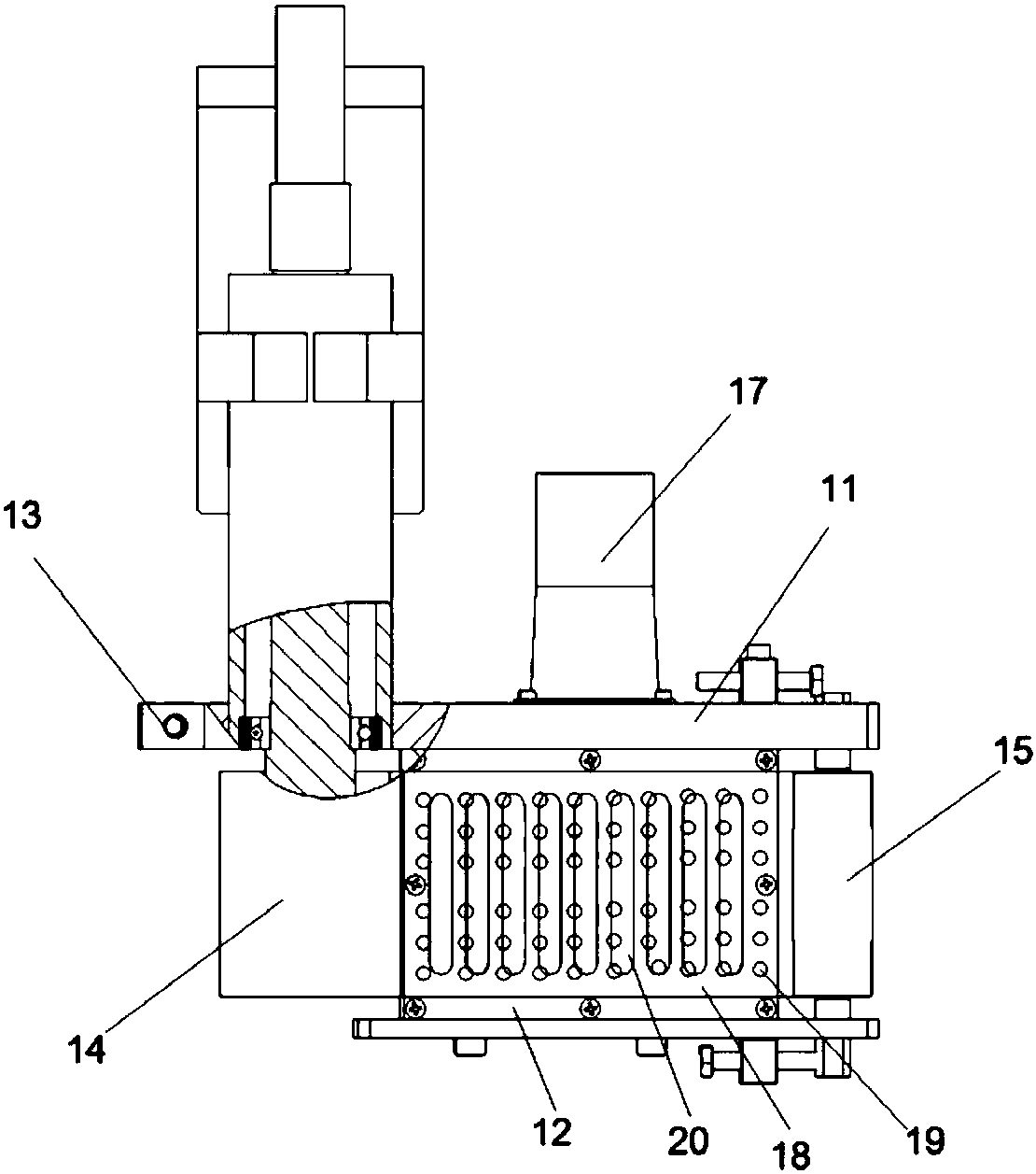
[0030] like Figure 1-3As shown, a release paper suction feeding and slitting application device includes a support backboard 1, a suction feeding mechanism and a slitting application mechanism installed on the support backboard 1 and matched with each other. Suction feeding mechanism comprises base 13, driving roller 14 installed on the base 13, tension roller 15, anti-adhesive conveying belt 18 tensioned on driving roller 14 and tension roller 15, anti-adhesive conveying belt 18 below. Suction box 16, anti-stick conveying belt 18 is provided with some first air suction holes 19, and slitting application mechanism comprises support, bottom roller 3 and cutter roller 2 installed on the support and the cutter roller 2 installed on the cutter roller. Knife 7 and the pressure roller ...


PUM


Abstract

The invention discloses a release paper suction feeding and cutting applying device which comprises a supporting back plate, a suction feeding mechanism and a cutting applying mechanism. The suction feeding mechanism comprises a base, a driving roller, a tension roller, an anti-sticking conveying belt and a suction box, the anti-sticking conveying belt is provided with a plurality of first suctionholes, the cutting applying mechanism comprises a support, a bottom roller, a cutter roller, a cutter and a pressing roller, the cutter is fixed to the cutter roller through a cutter frame, the widthof the cutter roller is larger than that of the cutter frame, the discharge position of the anti-sticking conveying belt corresponds to the release paper feeding position on the bottom roller, a cutting edge of the cutter is aligned to the release paper cut-off position on the bottom roller, the bottom roller is further provided with a pressing position, and the release paper cut-off position islocated between the release paper feeding position and the pressing position. The cut-off length of release paper can be conveniently controlled, the position of the cutter on the cutter roller can beadjusted according to requirements, therefore, the position of the release paper applied on main materials is adjustable within the main material front-side designated range, and products with different specifications can be conveniently produced.

Description

technical field [0001] The invention relates to parts of mechanical equipment, in particular to a release paper suction feeding and cutting application device. Background technique [0002] Medical pads are often compounded with some release paper stickers on the side or in the middle. Therefore, it is necessary to add special release paper conveying and release paper cutting and applying (compositing or pasting) devices to the medical pad production line; currently, the conventional The release paper conveying mechanism transports the release paper from the release paper roll to the release paper cutting application mechanism for cutting and application, and the cutting length of the release paper is difficult to control; and the conventional release paper cutting application mechanism generally The width of the cutter is the same as the width of the cutter roller, and the cutting width cannot be adjusted. When the width of the release paper is much smaller than the width o...

Claims


Application Information

Patent Timeline
IPC IPC(8): B65H35/08B65H5/22
CPCB65H35/08B65H5/226B65H2301/515323B65H2406/33B65H2701/194
Inventor 赵武军
Owner 杭州军锋机械有限公司
Learn More