
A power cable roller with its own retractable function

A technology of cable rollers and electric power, which is applied in the direction of cable installation, cable installation devices, electrical components, etc., can solve the problems of increased transportation costs, wear and tear of cable rollers, troublesome operation, etc., to save time for tying ropes, improve efficiency, and save cost effect

Inactive Publication Date: 2020-03-06
濮阳市创业机电工程有限公司
View PDF6 Cites 0 Cited by
  • Summary
  • Abstract
  • Description
  • Claims
  • Application Information

AI Technical Summary

Problems solved by technology

[0004] The main purpose of the present invention is to provide a power cable roller with its own retractable function, which can effectively solve the existing problem in the background technology that when the cable needs to be used, it is necessary to lift the cable roller through external equipment and then drive it to rotate. Retracting and unwinding the cable requires additional external equipment, and the external equipment also needs to be transported, which increases the transportation cost and troublesome operation. In the process of transporting the cable, the cable roller does not have the function of self-fixation, and the external fixation is unstable. It is easy to shake during transportation, causing friction and causing wear to the cable roller

Method used


Image

  • A power cable roller with its own retractable function
  • A power cable roller with its own retractable function
  • A power cable roller with its own retractable function

Examples


Embodiment

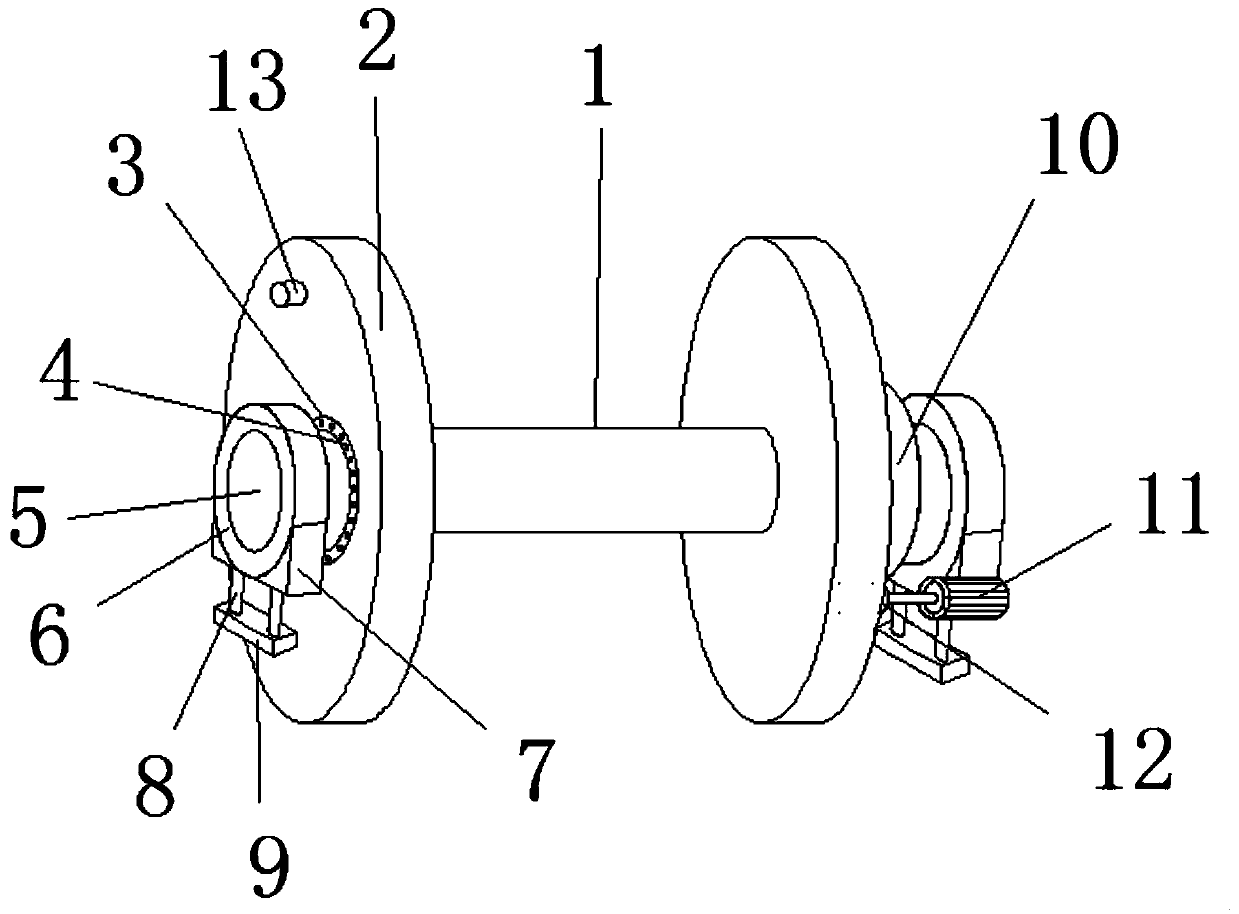
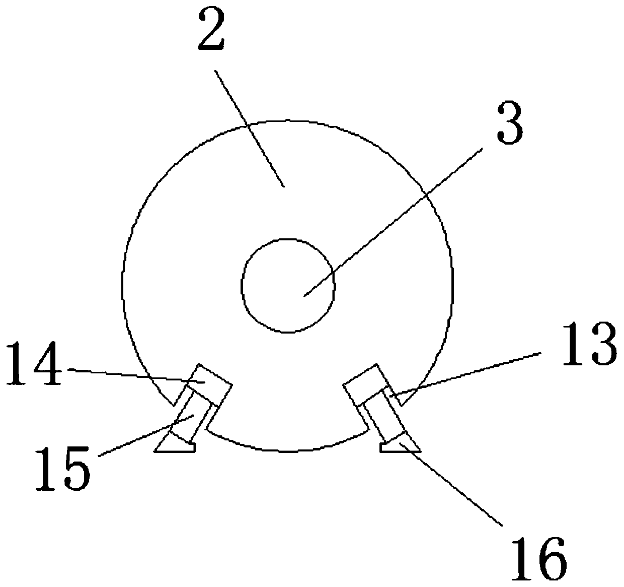
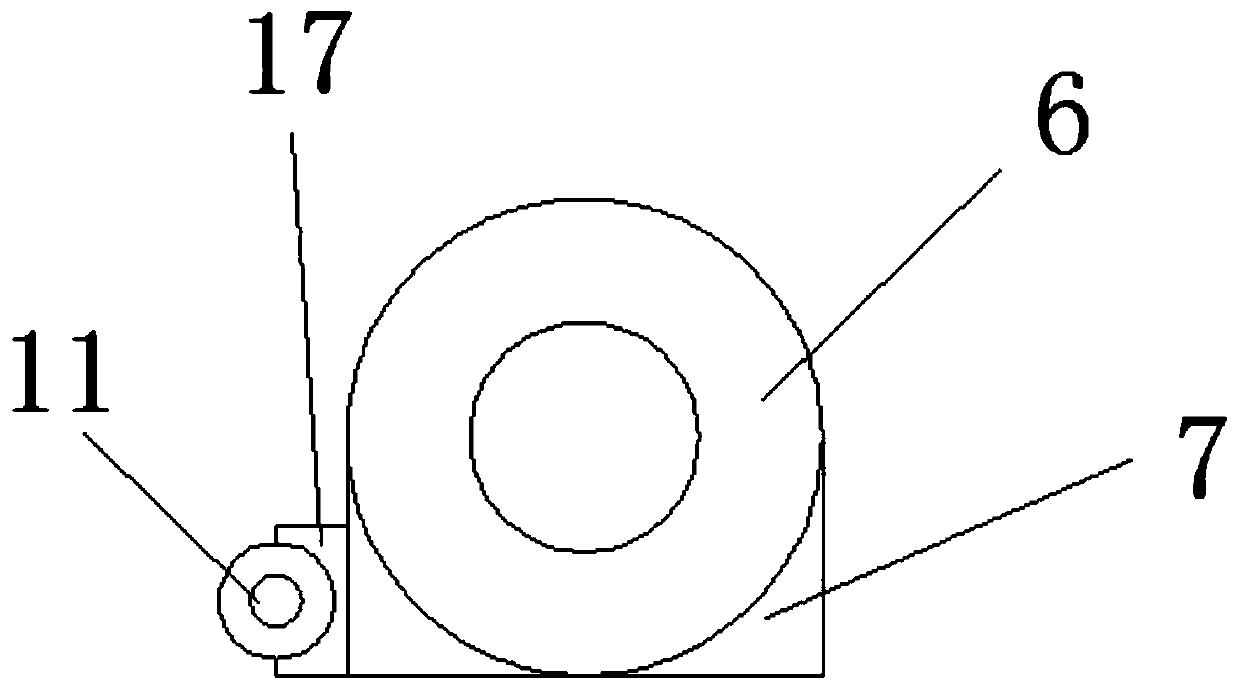
[0025] refer to Figure 1-4 , a power cable roller with its own retractable function, comprising a fixed tube 1, a disc 2, a first hydraulic cylinder 14 and a second hydraulic cylinder 19, both ends of the fixed tube 1 are fixedly connected to the disc 2, The middle of the outer wall of the disc 2 is provided with a through hole 3, and two groups of through holes 3 communicate with the two ends of the fixed pipe 1 respectively. The inner cavity of the through hole 3 is equipped with a bearing 4, and the disc 2 is made Rotatable, the inner cavity of the fixed tube 1 is equipped with a fixed shaft 5, the two ends of the fixed shaft 5 respectively pass through the two sets of bearings 4 and extend to the outside of the disc 2, the two ends of the fixed shaft 5 are A fixed ring 6 is sleeved, and the bottom of the fixed ring 6 is fixedly connected with a fixed seat 7, and one end of a second piston rod 8 is inserted on both sides of the bottom of the fixed seat 7, and the other end...


PUM


Abstract

The invention discloses a power cable roller with a winding and unwinding function. The power cable roller comprises a fixing pipe, disks, a first hydraulic cylinder and a second hydraulic cylinder. The disks are fixedly connected to two ends of the fixing pipe, through holes are formed in the middle positions of the outer walls of the disks, and the two groups of through holes communicate with the two ends of the fixing pipe. Bearings are installed in inner cavities of the through holes, and a fixing shaft is arranged in an inner cavity of the fixing pipe. According to the power cable rollerwith the winding and unwinding function, the second hydraulic cylinder is installed in a groove at the bottom of a fixing seat at the bottom of a fixing ring, through the work of the second hydrauliccylinder, a second piston rod drives a support block for support to enable the disks be to suspended, then a first gear is driven by a motor to rotate so as to rotate a second gear, so that the disksand the fixing pipe can rotate to achieve the effect of winding and unwinding of the cable, and the winding and unwinding function of the cable is achieved; and the power cable roller with the windingand unwinding function saves the cost of auxiliary winding and unwinding of transportation external equipment, and is more practical and suitable for extensive promotion and use.

Description

technical field [0001] The invention relates to a cable retracting device, in particular to a power cable roller with its own retracting function. Background technique [0002] The cable is usually a rope-like cable twisted by several or groups of wires [at least two in each group]. Each group of wires is insulated from each other and is often twisted around a center. Insulating covering. Most of them are erected in the air or installed underground or underwater for telecommunications or power transmission. In 1832, Schlinger, a veteran of Tsarist Russia, buried the telegraph line underground. The six conductors were insulated with rubber and placed in a glass tube. This is the earliest underground cable in the world. The existing cable is in the process of transportation. They are all wound on the cable roller. For example, Patent No. CN201420197269.9 discloses a cable pay-off self-rotating shaft disk. By placing the cable roller on the turntable, the cable roller is fixe...

Claims


Application Information

Patent Timeline
Patent Type & Authority Patents(China)
IPC IPC(8): B65H75/14B65H75/18B65H75/38B65H75/44H02G1/00
CPCB65H75/14B65H75/18B65H75/38B65H75/4486B65H2701/34H02G1/00
Inventor 叶泽洲
Owner 濮阳市创业机电工程有限公司
Learn More