A pole antenna bracket

An antenna bracket and rod antenna technology, which is applied to antennas, antenna supports/installation devices, antenna parts, etc., can solve the problems of unintuitive height adjustment, not easy to overlap, inconvenient to move, etc., so as to facilitate the overall movement , easy to operate, and the effect of improving safety

Active Publication Date: 2021-01-08
BEIJING INST OF RADIO METROLOGY & MEASUREMENT
View PDF12 Cites 0 Cited by
  • Summary
  • Abstract
  • Description
  • Claims
  • Application Information

AI Technical Summary

Problems solved by technology

[0003] This application proposes a rod antenna bracket, which aims to solve the following disadvantages of using a tripod to support the rod antenna in the prior art: (1) the bottom has no wheels, which is inconvenient to move; (2) height adjustment Unintuitive; (3) There is no support for the overlapping strap between the rod antenna and the test table, and it is not easy to overlap

Method used


Image

  • A pole antenna bracket
  • A pole antenna bracket
  • A pole antenna bracket

Examples


Embodiment 1

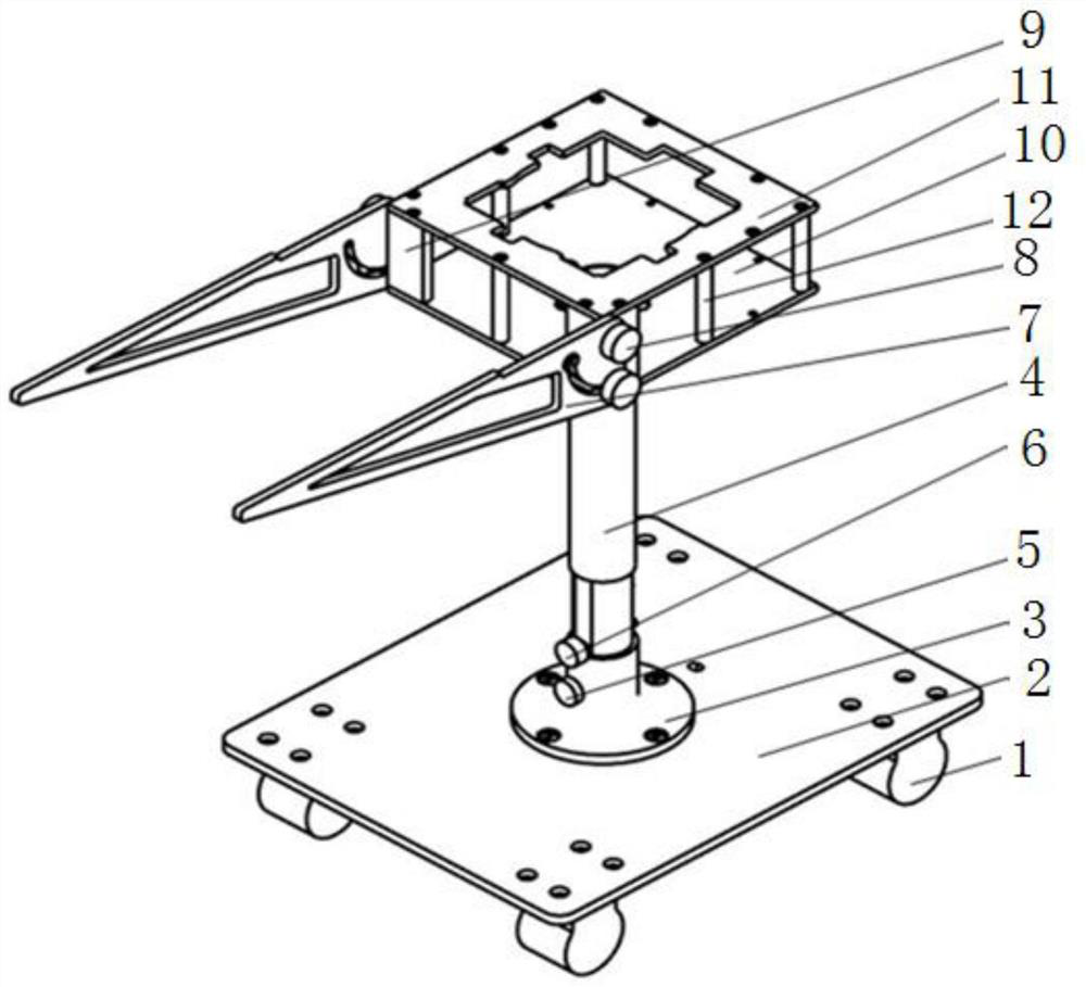
[0023] A rod antenna mount, see Figure 1 to Figure 4 , the antenna support includes a base 2, four casters 1 evenly distributed in a rectangular structure are installed under the base 2, and a cylindrical sleeve support 3 with an open upper end is installed on the base 2, see Figure 5 , the outer wall of the sleeve 4 is set as a stepped surface with the outer diameter of the lower part smaller than the outer diameter of the upper part, the outer wall of the lower part of the sleeve 4 is provided with a longitudinal plane, and the inner side wall of the sleeve support 3 is provided with a matching plane, the sleeve The lower part of 4 extends into the sleeve support 3, and the side wall of the sleeve support 3 is provided with a sleeve locking screw hole, and a sleeve locking screw 5 is arranged in the sleeve locking screw hole. The bottom of cylinder 4 is provided with transverse pin hole, see Figure 6 , the pin hole is provided with a bolt 6, and the pin hole is located a...

Embodiment 2

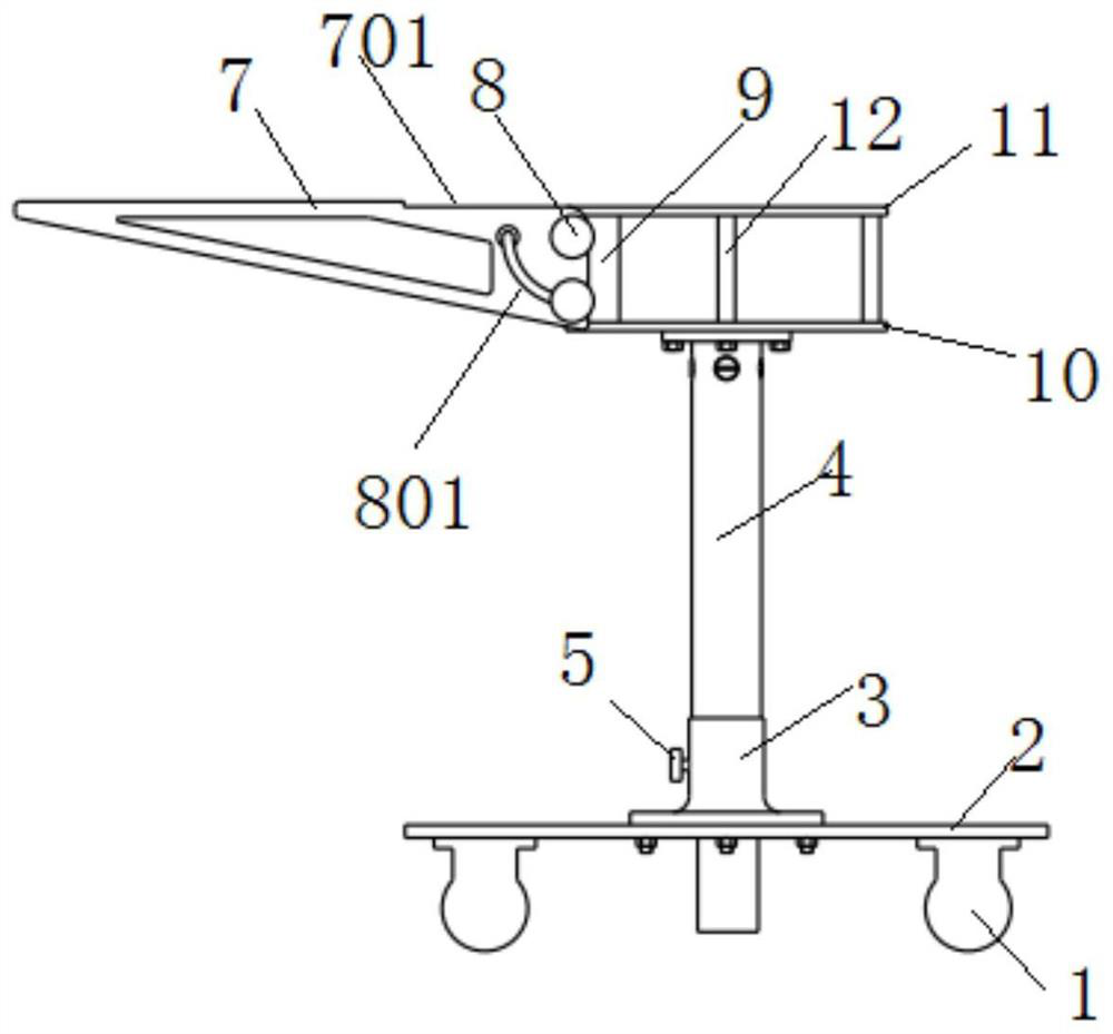
[0026] A rod antenna bracket, similar to Embodiment 1, the difference is that the lap support plate 7 is respectively connected to the outer side of the lap plate supporting fixed corner block 9 through two lap locking screws 8, one of which is lapped The locking screw 8 is located in the sliding groove 801 .

[0027] It may be further possible that, among the two overlapping locking screws 8 of the overlapping support plate 7 , the lower overlapping locking screw 8 is located in the slide groove 801 .

Embodiment 3

[0029] A rod antenna bracket, similar to Embodiment 1 or Embodiment 2, the difference is that the annular hole on the supporting plate 11 of the rod antenna is a cross-shaped hole.

[0030] Furthermore, the overlapping supporting plate 7 is a right-angled triangular plate whose top side is a horizontal side.

[0031] Furthermore, the right side of the overlapping support plate 7 is a vertical side.

[0032] Furthermore, hollow holes are provided on the overlapping support plate 7 . The hollow hole can also be a right triangle. And the side of the hollow hole is preferably parallel to the side of the adjacent overlapping support plate 7 .

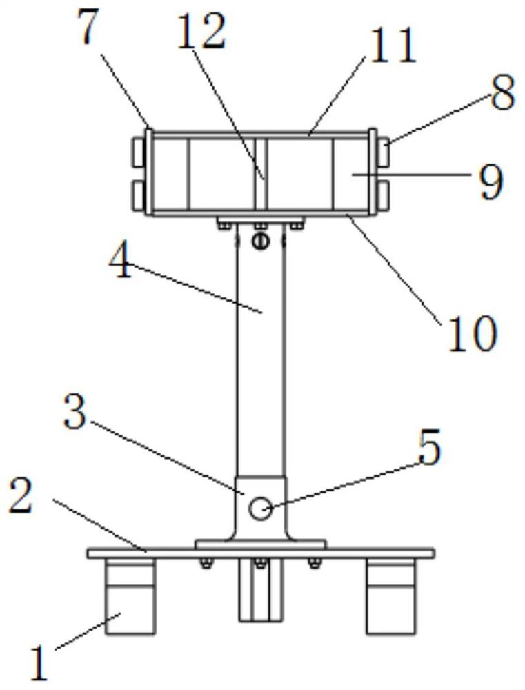
[0033] Furthermore, the longitudinal centerlines of the base 2 , the sleeve support 3 , the sleeve 4 , the lower support plate 10 of the rod antenna and the upper support plate 11 of the rod antenna coincide.

[0034] The rod antenna support, as a height adjustment device suitable for old and new standards, can be adjusted in one step; an...


PUM


Abstract

The invention discloses a pole antenna support. Trundles are arranged under a base, a sleeve support is mounted on the base, and the lower part of the sleeve extends into the sleeve support. A sleevelocking screw is arranged on the side wall of the sleeve support, a bolt is arranged at the lower part of the sleeve, and the upper end of the sleeve is connected with a pole antenna lower supportingplate. A pole antenna upper supporting plate is arranged above the pole antenna lower supporting plate, the lap joint plate supporting and fixing angle blocks and the pole antenna supporting plate supporting columns are connected between the pole antenna lower supporting plate and the pole antenna upper supporting plate, and the outer sides of the lap joint plate supporting and fixing angle blocksare connected with the lap joint supporting plates through the lap joint locking screws respectively. A sliding groove of a lower left quarter arc through hole structure is formed on each lap joint supporting plate, and the lap joint locking screws are arranged in the sliding grooves, and the right ends at the upper parts of the lap joint supporting plates are equipped with the step sections. With the trundles, the pole antenna support can be conveniently and integrally moved, the height of the pole antenna support can be conveniently and quickly adjusted, the pole antenna support is easy andconvenient to operate and is suitable for new and old standard heights. A lap joint belt can be conveniently arranged in the testing process, the pole antenna support has the folding and unfolding functions, the occupied space of the support is reduced, and the safety is improved.

Description

technical field [0001] The present application relates to the technical field of brackets, in particular to a rod antenna bracket. Background technique [0002] The electromagnetic compatibility radiation emission (RE) test is a very important test item in the existing test military standard. This test needs to be carried out no matter it is on the ground, on the ship, or on the air. It can be said that it is a measure of an electronic device or subsystem. key indicators. The RE102 test item in the RE test is described in GJB151 as: 10kHz~18GHz electric field radiation emission. From the perspective of the frequency band, the frequency range of this test item covers a very wide range. No matter what platform the RE102 test is for, it covers the pole antenna (the frequency range is 10kHz to 30MHz). In GJB152A-1997 (old standard) and GJB151B-2013 (new standard), the test configuration of the rod antenna is specified respectively. Among them, GJB152A-1997 stipulates that the...

Claims


Application Information

Patent Timeline
Patent Type & Authority Patents(China)
IPC IPC(8): H01Q1/12H01Q3/04
CPCH01Q1/12H01Q1/1242H01Q3/04
Inventor 黄承祖韩玉峰袁岩兴穆晨晨刘阳
Owner BEIJING INST OF RADIO METROLOGY & MEASUREMENT
Why Eureka
Try Eureka