Combined type fuel tank with three tanks

A combined, fuel tank technology, applied in the layout combined with the fuel supply of the internal combustion engine, the electronic control of the exhaust gas treatment device, the exhaust gas treatment, etc., can solve the problem of no patent application, etc., to solve the installation and layout problems, and facilitate maintenance. , the effect of beautiful appearance

Inactive Publication Date: 2012-05-16
FAW GROUP
View PDF0 Cites 4 Cited by
  • Summary
  • Abstract
  • Description
  • Claims
  • Application Information

AI Technical Summary

Problems solved by technology

[0008] Searching patents found that there

Method used


Image

  • Combined type fuel tank with three tanks
  • Combined type fuel tank with three tanks
  • Combined type fuel tank with three tanks

Examples


Embodiment 1

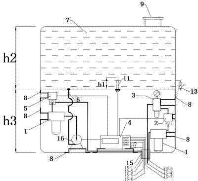
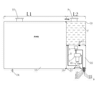
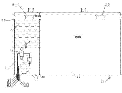
[0030] The selected material is SUS304 or SUS441 stainless steel plate, its thickness is 1.2mm, the volume capacity relation L1 / L2=5 of fuel tank body 12 and reductant tank body 7; It is made of holes, rolled plates, and welded. After being installed on the car, it can be seen that the fuel tank 12 is arranged on the car at the farthest distance from the engine, while the urea reducing agent box 7 and the electrical control box 20 are arranged on the car. The position is the closest to the engine, and the combined fuel tank is fixed on the vehicle frame with a bracket; the urea reducing agent tank cover 9 and the fuel tank cover 10 are facing the outside of the compartment; wherein, the fuel tank body 12 and the urea reducing agent tank body 7 Complete the 30min pressure seal test under the constant pressure of 0.08Mpa; the ratio of the height h1 of the urea reducing agent liquid level sensor 11 to the height h2 of the reducing agent tank 7 is h1 / h2=1 / 5; the urea reducing agent...

Embodiment 2

[0032] The selected material is SUS304 or SUS441 stainless steel plate, its thickness is 1.4mm, the volume capacity relationship L1 / L2=10 between fuel tank body 12 and reductant tank body 7; Holes, rolled plates, and welding are made into fuel tank 12, urea reducing agent box 7 and electrical control box 20 respectively. After the combined fuel tank is installed on the vehicle, the fuel tank 12 is arranged on the vehicle. It is the farthest from the engine, and the position on the vehicle where the urea reducing agent box 7 and the electrical control box 20 are arranged is the closest to the engine. The combined fuel tank is fixed on the vehicle frame with a bracket; the urea reducing agent box The cover 9 and the fuel tank cover 10 are facing the outside of the compartment; at the same time, the full scale fuel and urea reducing agent are filled, the consumption rate of the urea reducing agent is 1 / 20~1 / 25 of the fuel, and the amount of the two liquids can be maintained almost...

Embodiment 3

[0034] The selected material is SUS304 or SUS441 stainless steel plate, its thickness is 1.4mm, the volume capacity relation L1 / L2=15 of fuel tank body 12 and reductant tank body 7; Holes, rolled plates, and welding are made into fuel tank 12, urea reducing agent box 7 and electrical control box 20 respectively. After the combined fuel tank is installed on the vehicle, the fuel tank 12 is arranged on the vehicle. It is the farthest from the engine, and the position on the vehicle where the urea reducing agent box 7 and the electrical control box 20 are arranged is the closest to the engine. The combined fuel tank is fixed on the vehicle frame with a bracket; the urea reducing agent box The cover 9 and the fuel tank cover 10 face the outside of the compartment; among them, the fuel tank 12 and the urea reducing agent tank 7 have completed a 30-min pressurization and sealing test at a constant pressure of 0.08Mpa; the height h1 of the urea reducing agent liquid level sensor 11 an...


PUM


Abstract

The invention relates to a combined type fuel tank with three tanks; the combined type fuel tank comprises a precise filter, a precise gas electromagnetic valve, a precise pressure maintaining valve, a control unit, a precise liquid electromagnetic valve, a pre-pumping and post-pumping urea reducing agent tube, a urea reducing agent tank body, a metallic support, a urea reducing agent tank cover, a fuel tank cover, a urea reducing agent liquid level sensor, a fuel tank body, a urea reducing agent tap valve, a fuel tap valve, a combined casing pipe getting into and getting out of an electric control cabinet, a urea reducing agent dosage pipe, a power source lead wire, a compressed air input pipe, a compressed air output pipe, a temperature feedback signal wire from a catalytic converter, a nitric oxide feedback signal wire from the catalytic converter, a urea reducing agent liquid level alarm signal wire input into a cab, a miniature liquid pump, a natural vent opening, a tank body connecting soldering point, a seaming end cover pinch board and an electric control cabinet; the combined type fuel tank is characterized in that the fuel tank body is arranged at one side of the fuel tank, the urea reducing agent tank body is arranged at the upper part of the other side of the fuel tank, and the electric control cabinet is arranged at the lower part of the other side of the fuel tank; a volume capacity relationship between the fuel tank body and the reducing agent tank body is L1/L2=5-15, the volume relationship between the reducing agent tank body and the electric control cabinet is h3/h2=1; and the seaming end cover pinch board is arranged at one side of the electric control cabinet. The combined type fuel tank has the advantages that the compactness design is realized, the beautiful design of vehicles is facilitated, the installation of connecting members is reduced, the vehicle configuration is simplified, the weight is reduced, the standard requirement of SCR (Selective Catalytic Reduction) adopting by National IV and the above is satisfied and the cost of systems is also reduced.

Description

technical field [0001] The invention relates to a three-tank composite combined fuel tank, which is applied to the post-treatment industry of automobile exhaust. Background technique [0002] In the next few years, automobile manufacturers around the world, especially the United States and Europe, will enforce some stricter standards on vehicle nitrogen oxides NOx and particulate PM emissions, such as Euro V and Euro VI emission standards. [0003] Under the pressure of emission regulations, on the one hand, foreign heavy-duty diesel engines for vehicles are constantly upgrading and improving their technology; , DPF (Diesel Particulate Filter) particle trap, DOC (Diesel Oxidation Catalyst) oxidation catalyst, etc. [0004] The essence of SCR technology is to use urea to decompose NH at high temperature 3 , NH as reducing agent 3 and NO in engine exhaust x The reaction is carried out under the combined action of catalyst and temperature, and under ideal conditions, non-to...

Claims


Application Information

Patent Timeline
IPC IPC(8): F02M37/00F01N9/00F01N3/24B60K15/063
CPCY02T10/47Y02A50/20Y02T10/40
Inventor 张克金崔龙王丹张苡铭李凤伟魏晓川杨彬刘国军
Owner FAW GROUP
Why Eureka
Try Eureka