Fender mounting bracket of automobile

A technology for automobile fenders and mounting brackets, which is applied to vehicle components, transportation and packaging, and upper structures, and can solve problems such as damage to the cable skin, cable skin damage, and dimensional errors, so as to ensure the dimensional accuracy of the final assembly and improve Installation strength, simple structure and practical effect

Active Publication Date: 2011-06-15
CHONGQING CHANGAN AUTOMOBILE CO LTD
View PDF4 Cites 11 Cited by
  • Summary
  • Abstract
  • Description
  • Claims
  • Application Information

AI Technical Summary

Problems solved by technology

Due to the increased rounded corners on the left and right sides of the front, the shape of the headlights is more complicated, and the position is moved to the side, so that the engine front cabin side beam must be shortened, and the traditional fender mounting bracket cannot be installed from the front side to the side of the engine front cabin side beam on the surface
In order to solve this problem, the traditional method is to move the installation position of the fender and the mounting bracket of the fender to the rear following the shortening of the front cabin of the engine, resulting in an increase in the suspension size of the front end of the fender
In doing so, the strength of the front end of the fender is reduced, and the noise and vibration cannot be controlled; the cables required for the headlights and other electrical components in the cabin must be arranged near the edge beam of the front cabin of the engine, but it is easy to receive the

Method used


Image

  • Fender mounting bracket of automobile
  • Fender mounting bracket of automobile
  • Fender mounting bracket of automobile

Examples


Embodiment Construction

[0016] The present invention will be further described below in conjunction with the accompanying drawings.

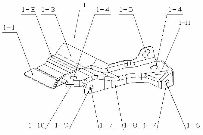
[0017] see figure 1 In the shown car fender mounting bracket, the main body 1 is a sheet metal part formed by stamping, the upper surface 1-11 of the main body is in the shape of a long strip, and the left part is convex and the right part is straight;

[0018] The rear edge of the left part of the upper surface 1-11 of the body is bent downward and connected with the straight first welding surface 1-1, the coordination rib 1-2 and the upwardly bent second welding surface 1-3;

[0019] The rear edge of the right part of the upper surface 1-11 of the body is turned upwards, the left end of the turn is connected with the second welding surface 1-3, and a strip-shaped wiring harness installation hole 1-5 is provided on the right end of the turn; The car wiring harness can pass through the bend of the body of the fender mounting bracket, and the wiring harness can be fixe...


PUM


Abstract

The invention discloses a fender mounting bracket of an automobile. The upper surface of a body is long strip-shaped and the bracket is characterized in that: the back side on the left part of the upper surface of the body is bent downwards and is connected with a smooth and level first solder side, a coordinating rib and a second solder side which is bent upwards; the back side on the right part of the upper surface of the body is bent upwards, the left end of the bent part is connected with the second solder side and the right end of the bent part is provided with a wire harness mounting hole; the left end in front of the upper surface of the body is provided with a downward flanged reinforcing rib; other parts in front of the upper surface of the body are bent downwards and are connected with a first fender mounting surface and a second fender mounting surface; and the first fender mounting surface and the second fender mounting surface are provided with a fender mounting hole respectively. By the bracket, the problem of mounting a fender is solved, spaces are effectively utilized, intensity is improved, the dimension and the overall dimensional accuracy of the bracket are ensured and an integrated mounting position is provided for a wire harness; and the bracket has the advantages of simple and practical structure, low cost and the like and is safe and reliable.

Description

technical field [0001] The invention relates to automobile body components, in particular to an automobile fender mounting bracket. Background technique [0002] Most of the mounting brackets for automobile fenders on the market are in the shape of a simple "several", and are installed on the side surface of the side beam of the front cabin of the automobile engine. With the intensification of competition in the automotive industry, the importance of automotive exterior design is becoming more and more important, especially the shape of the front face and front design of the car is becoming more and more complex. In order to adapt to this changing trend, the structure of the front cabin of the engine must undergo major changes following the exterior design. Due to the increased rounded corners on the left and right sides of the front, the shape of the headlights is more complicated, and the position is moved to the side, so that the engine front cabin side beam must be shor...

Claims


Application Information

Patent Timeline
IPC IPC(8): B62D21/09B62D25/16
Inventor 戴路乔俊朋谷小渝
Owner CHONGQING CHANGAN AUTOMOBILE CO LTD
Why Eureka
Try Eureka