
A color steel tile laying device

A color steel tile, tile shop technology, applied in the direction of roofing, construction, building structure, etc., can solve the problems of workers' hand cuts, falling accidents, etc., to reduce potential safety hazards, improve construction safety, reduce falls and injuries. Effects of electric shock risk

Active Publication Date: 2019-03-08
HAINAN ZHEDA STEEL STRUCTURE ENG
View PDF6 Cites 0 Cited by
  • Summary
  • Abstract
  • Description
  • Claims
  • Application Information

AI Technical Summary

Problems solved by technology

During the installation of color steel tiles, the workers carry the color steel tiles to the roof, and fix them after moving the color steel tiles to the corresponding position on the roof. The workers are prone to fall accidents during the roof climbing process, and the color steel tiles are in the color steel tiles. The end face of the steel tile is sharp, which is easy to cut the worker's hand

Method used


Image

  • A color steel tile laying device
  • A color steel tile laying device
  • A color steel tile laying device

Examples


Embodiment 1

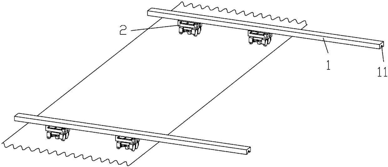
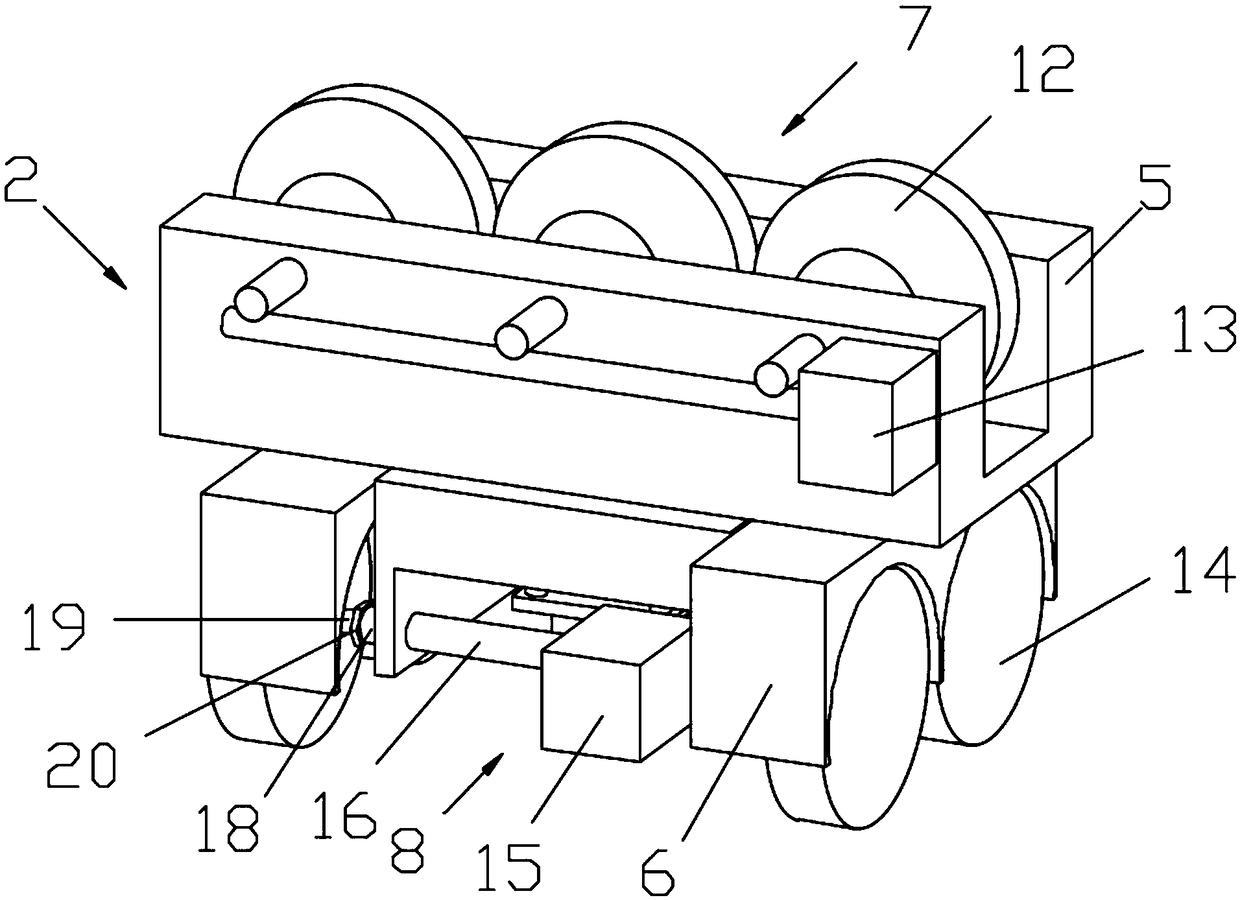
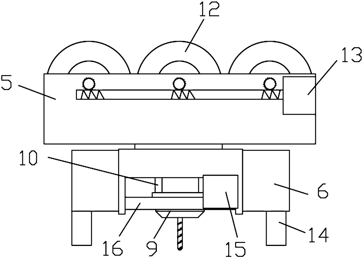
[0022] see Figures 1 to 5 , a color steel tile laying device, including a guide rail 1, a carrier 2, an electric drill 9, a controller 3 and a remote control terminal 4, the number of the guide rails 1 is at least two and they are arranged parallel to each other on the roof. The device 2 includes a first electromagnet 5, a second electromagnet 6, a first drive mechanism 7 and a second drive mechanism 8, and the carrier 2 is adsorbed on the bottom of the guide rail 1 by the first electromagnet 5, and the carrier 2 2 The color steel tile is adsorbed by the second electromagnet 6, the first driving mechanism 7 drives the carrier 2 to move along the guide rail 1, and the second driving mechanism 8 drives the carrier 2 to move along the color steel tile concave The slot moves, the electric drill 9 is installed on the bottom of the carrier 2 through the electric telescopic rod 10, the first electromagnet 5, the second electromagnet 6, the first drive mechanism 7, the second drive m...

Embodiment 2

[0029] see Figures 1 to 5 The difference between this embodiment and Embodiment 1 is that the number of the second rollers 14 is at least two, and the second rollers 14 are connected to each other through a connecting shaft 16, and the connecting shaft 16 is connected to the second roller through a transmission mechanism. The motor 15 is connected. Improve the firmness of the adsorption between the carrier 2 and the color steel tile, avoid the deviation of the carrier 2 during the punching process of the device, and improve the quality of the punching, thereby improving the installation firmness of the color steel tile and improving the color steel tile. The firmness of the connection between them can avoid damage to the roof caused by typhoon weather and improve the service life of the color steel tile.

[0030] Specifically, the transmission mechanism is a worm gear 17 transmission. The roof of the color steel tile is an inclined roof, and the carrier 2 will slide down du...


PUM


Abstract

The invention discloses a colored steel tile laying device. The colored steel tile laying device comprises at least two guide rails, carriers, electric drilling machines, a controller and a remote control terminal. The guide rails are parallelly arranged on a roof, each carrier comprises a first electromagnet, a second electromagnet, a first driving mechanism and a second driving mechanism, and the carriers are attracted to the bottoms of the guide rails through the first electromagnets and attract colored steel tiles through the second electromagnets; the first driving mechanisms drive the carriers to move along the guide rails, the second driving mechanisms drive the carriers to move along grooves of the colored steel tiles, and the electric drilling machines are installed at the bottomsof the carriers through electric retractable rods; the first electromagnets, the second electromagnets, the first driving mechanisms, the second driving mechanisms, the electric drilling machines, the electric retractable rods and the remote control terminal are separately connected with the controller. The colored steel tiles can be moved to required positions and drilled, and potential safety hazards of construction are reduced.

Description

technical field [0001] The invention relates to the technical field of color steel tile installation equipment, in particular to a color steel tile laying device. Background technique [0002] Color steel tiles are suitable for roofs, walls and interior and exterior wall decoration of industrial and civil buildings, warehouses, special buildings, and large-span steel structure houses. , long life, maintenance-free and other characteristics, has been widely promoted and applied. During the installation of color steel tiles, the workers carry the color steel tiles to the roof, and fix them after moving the color steel tiles to the corresponding position on the roof. The workers are prone to fall accidents during the roof climbing process, and the color steel tiles are in the color steel tiles. The end face of the steel tile is sharp, which is easy to cut the worker's hand. Contents of the invention [0003] In view of the above-mentioned prior art, the present invention pr...

Claims


Application Information

Patent Timeline
Patent Type & Authority Patents(China)
IPC IPC(8): E04D15/02
CPCE04D15/02
Inventor 方建平陈炜
Owner HAINAN ZHEDA STEEL STRUCTURE ENG
Learn More