Multifunctional power supply combiner box

A power confluence and multi-function technology, applied in the field of combiner boxes, can solve the problems of no fire extinguishing function, limited heat dissipation effect, exposed installation structure, etc., and achieve the effect of effective fire control, remarkable heat dissipation effect, and easy installation and disassembly.

Inactive Publication Date: 2018-09-11
ZAOZHUANG JINWANTONG ELECTRONICS PROD CO LTD
View PDF0 Cites 4 Cited by
  • Summary
  • Abstract
  • Description
  • Claims
  • Application Information

AI Technical Summary

Problems solved by technology

The device can ensure that the photovoltaic system is easy to cut off the circuit during maintenance and inspection, and reduce the scope of power outage when the photovoltaic system fails. Then connect several photovoltaic series in parallel to the photovoltaic combiner box. After converging in the photovoltaic combiner box, the controller, DC power distribution cabinet, photovoltaic inverter, and AC power distribution cabinet are used together to form a complete system. Photovoltaic power generation system realizes grid connection with mains power, but the existing combiner box has poor waterproof performance, limited heat dissipation effect, and the exposed installation structure is not convenient for storage, and has no fire extinguishing function

Method used


Image

  • Multifunctional power supply combiner box
  • Multifunctional power supply combiner box
  • Multifunctional power supply combiner box

Examples


Embodiment Construction

[0021] The following will clearly and completely describe the technical solutions in the embodiments of the present invention with reference to the accompanying drawings in the embodiments of the present invention. Obviously, the described embodiments are only some, not all, embodiments of the present invention. Based on the embodiments of the present invention, all other embodiments obtained by persons of ordinary skill in the art without making creative efforts belong to the protection scope of the present invention.

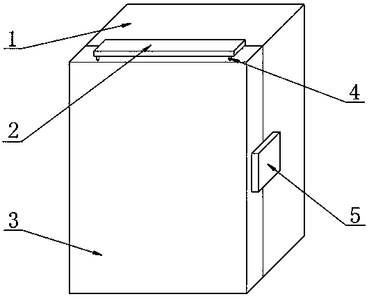
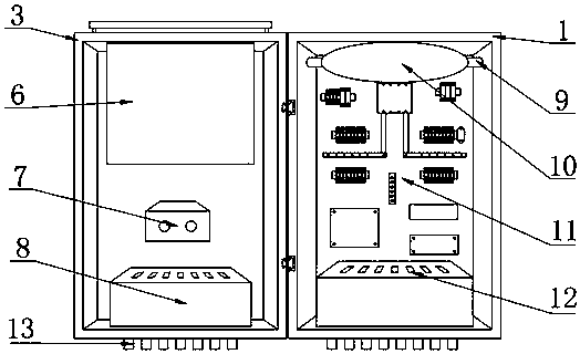
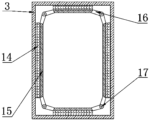
[0022] see Figure 1-6 , the present invention provides a technical solution: a multifunctional power combiner box, including a combiner box 1, a top plate 2, a box door 3, a connecting column 4, a lock 5, a cooling box 6, an anti-backflow switch 7, a battery 8, Fixing rod 9, rubber bag 10, component assembly 11, interface 12, joint 13, water-swellable water-stop strip 14, baffle plate 15, arc rod 16, rotating shaft 17, cover plate 18, magnetic stone 19, pull ...


PUM


Abstract

The invention discloses a multifunctional power supply combiner box. The multifunctional power supply combiner box comprises a combiner box body, a top plate, a box door, a connecting pillar, a lock,a heat dissipation box body, an anti-backflow switch, a storage battery, fixed links, a rubber capsule, a component module, an interface, a joint, waterproof rubber, a baffle, an arc-shaped rod, a rotating shaft, a cover plate, magnetic stones, a buckle, a groove, a mounting rod, a mounting plate, a mounting hole, a through hole, moisture absorption cotton, a heat dissipation scale, a fan blade, aheat conducting plate and a motor, wherein the rubber capsule is fixedly arranged at the top of each of the two sides of the inner wall of the combiner box body by virtue of two fixed links, the component module is fixedly arranged on the inner wall of the combiner box body, the box door is mounted one side of the combiner box body by virtue of a hinge, the lock is mounted at a joint of the otherside of the combiner box body and the box door, the waterproof rubber is arranged at the inner sides of the joint of the combiner box body and the box door respectively, and the inner side of the waterproof rubber is connected with the baffle. The combiner box has good waterproof performance and obvious heat dissipation effect, is easy to mount and store and also has a fire extinguishing function.

Description

technical field [0001] The invention relates to the technical field of combiner boxes, in particular to a multifunctional power combiner box. Background technique [0002] In the photovoltaic power generation system, the combiner box is a wiring device to ensure the orderly connection and confluence function of photovoltaic modules. The device can ensure that the photovoltaic system is easy to cut off the circuit during maintenance and inspection, and reduce the scope of power outage when the photovoltaic system fails. Then connect several photovoltaic series in parallel to the photovoltaic combiner box. After converging in the photovoltaic combiner box, the controller, DC power distribution cabinet, photovoltaic inverter, and AC power distribution cabinet are used together to form a complete system. The photovoltaic power generation system realizes grid connection with the mains, but the existing combiner box has poor waterproof performance, limited heat dissipation effect...

Claims


Application Information

Patent Timeline
Patent Type & Authority Applications(China)
IPC IPC(8): H02S40/34H02S40/30
CPCH02S40/30H02S40/34Y02A30/14Y02E10/50
Inventor 高鹏高房
Owner ZAOZHUANG JINWANTONG ELECTRONICS PROD CO LTD
Why Eureka
Try Eureka