Gyro-flywheel toy
A technology of gyro flywheel and toys, which is applied in the directions of gyro, toys, entertainment, etc., can solve problems such as difficult control, and achieve the effect of simple operation and good entertainment.
- Summary
- Abstract
- Description
- Claims
- Application Information
AI Technical Summary
Problems solved by technology
Method used
Image

Examples
Embodiment 1
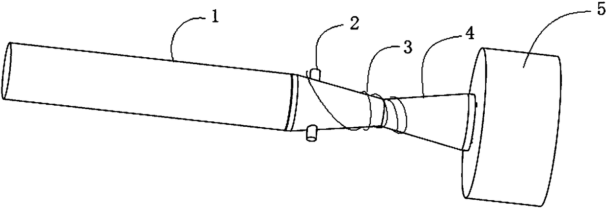
[0028] Such as figure 1 As shown, a spinning top flywheel toy disclosed in this embodiment includes a handle 1, a driving part 4, a drawstring 3 and a flywheel 5. The handle 1 is movably connected to the driving part 4, so that the driving part 4 can take the axis of the handle 1 as the axis Rotate, the stay cord 3 is wound on the drive part 4 in use state, and the drive part 4 is rotated by pulling the stay cord 3 when driving, the end of the drive part 4 is provided with a pin 10, and the flywheel 5 is provided with Socket 13 that matches pin 10, such as Figure 6 shown.
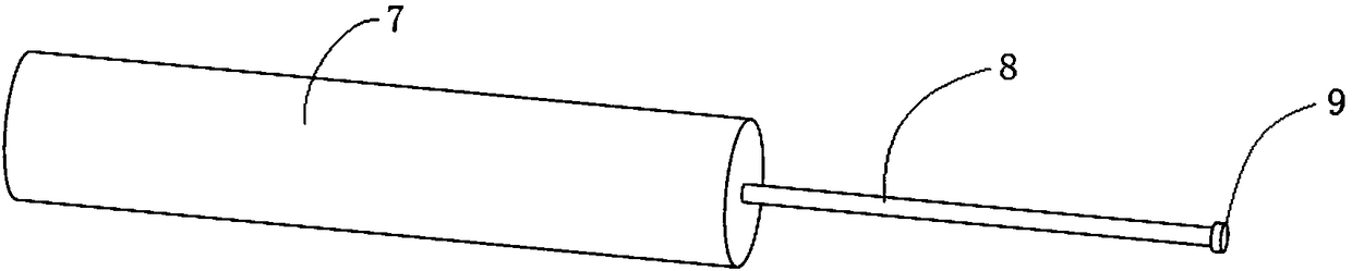
[0029] Such as image 3 As shown, the handle 1 shown includes a grip part 7, a center rod 8 and an anti-off cap 9, the center rod 8 is fixed at the center of the grip part 7 by means of plugging, and the other end of the center rod 8 is provided with an anti-off cap 9 to prevent The uncapping 9 can be fixed on the central rod 8 by threaded connection, and is used to prevent the driver 4 from coming off....
Embodiment 2
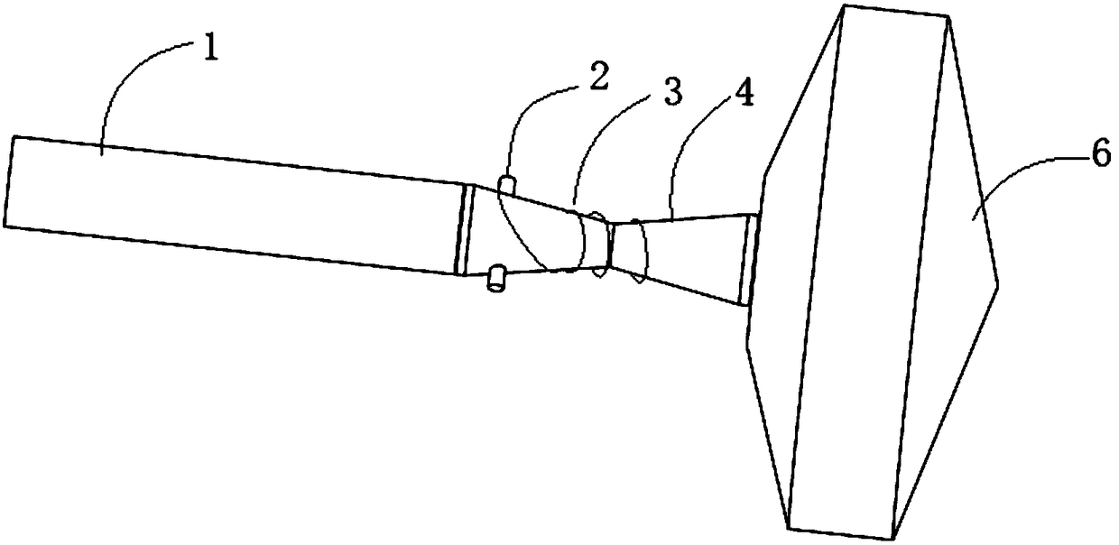
[0035] Such as figure 2 , a spinning top flywheel toy disclosed in this embodiment, comprising a handle 1, a driving part 4, a drawstring 3 and a top 6, the handle 1 is movably connected to the driving part 4, so that the driving part 4 can rotate around the axis of the handle 1, The stay cord 3 is wound on the driving part 4 in use state, and the driving part 4 is rotated by pulling the stay cord 3 when driving. pin 10 matches jack 13, such as Figure 7 shown.
[0036] Such as image 3 As shown, the handle 1 shown includes a grip part 7, a center rod 8 and an anti-off cap 9, the center rod 8 is fixed at the center of the grip part 7 by means of plugging, etc., and the other end of the center rod 8 is provided with an anti-off cap 9 for use To prevent the driver 4 from coming off.
[0037] Such as Figure 4 As shown, the driving part 4 shown is a cylindrical structure that is thinner in the middle and thicker toward both ends. A through hole is provided at the axis of th...
Embodiment 3
[0040] Such as Figure 5 , the technical solution of this embodiment is basically the same as that of Embodiment 2 or 3, the only difference is that in this implementation, the driving member 4 is a cylindrical structure, and the outer surface of the driving member 4 is provided with an annular groove for winding a stay cord 12. Further, the driving member 4 is provided with a hanging post ( Figure 5 Not shown in the middle), the wire hanging post is a protrusion arranged perpendicular to the axial direction of the driving member. Still further, there are two wire hanging posts, which are symmetrically arranged on both sides of the driving member. When winding the stay cord on the driver 4, first make one end of the stay cord 3 be in the shape of a collar, and then hang the collar on the hanging wire post for winding, which greatly facilitates the user's use.
PUM
 Abstract
Description
Claims
Application Information
 - R&D Engineer
- R&D Manager
- IP Professional
- Industry Leading Data Capabilities
- Powerful AI technology
- Patent DNA Extraction
Browse by: Latest US Patents, China's latest patents, Technical Efficacy Thesaurus, Application Domain, Technology Topic.
© 2024 PatSnap. All rights reserved.Legal|Privacy policy|Modern Slavery Act Transparency Statement|Sitemap