Brake release mechanism and medical manipulator provided with same

a technology of a which is applied in the field of brake release mechanism and a medical manipulator provided with the same, can solve the problems of deteriorating responsiveness to operations of the operating member, difficult carrying out procedures, and still affecting the angle of the end effector by such a reaction force, so as to enhance the ease of operation, release easily and quickly, and enhance the effect of ease of operation

Active Publication Date: 2018-09-04
KARL STORZ GMBH & CO KG
View PDF16 Cites 768 Cited by
  • Summary
  • Abstract
  • Description
  • Claims
  • Application Information

AI Technical Summary

Benefits of technology

[0009]The present invention has been devised while taking into consideration the aforementioned problems, and has the object of providing a brake release mechanism which is capable of easily and swiftly releasing a braking action performed by a brake mechanism, even with one hand, and a medical manipulator equipped with such an brake release mechanism.
[0022]The brake release mechanism of the present invention enables a braking action performed by the brake mechanism to be released easily and swiftly even with one hand. In accordance with the medical manipulator of the present invention, both the release button and the operating member can be operated with one hand, whereby ease of operation can be enhanced.

Problems solved by technology

However, if an operating member (operating dial) is manually operated to carry out tilting of the end effector, in the event that the living tissue is pressed by the end effector, the angle of the end effector still tends to be changed by such a reaction force.
However, such an action is troublesome, and carrying out procedures is difficult.
However, when such a worm gear is used, it becomes necessary for the operating member to be turned many times in order to change the angle of the end effector, and responsiveness to operations of the operating member is deteriorated.
Alternatively, even in the case that the release button is arranged in proximity to the operating member so that the user can operate both the release button and the operating member with one hand, operation of both the release button and the operating member with one hand is not easily performed, and operability is adversely affected.

Method used


Image

  • Brake release mechanism and medical manipulator provided with same
  • Brake release mechanism and medical manipulator provided with same
  • Brake release mechanism and medical manipulator provided with same

Examples


Embodiment Construction

[0035]Hereinafter, a preferred embodiment of a brake release mechanism and a medical manipulator according to the present invention will be described in detail below with reference to the accompanying drawings.

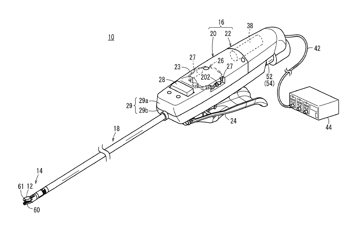
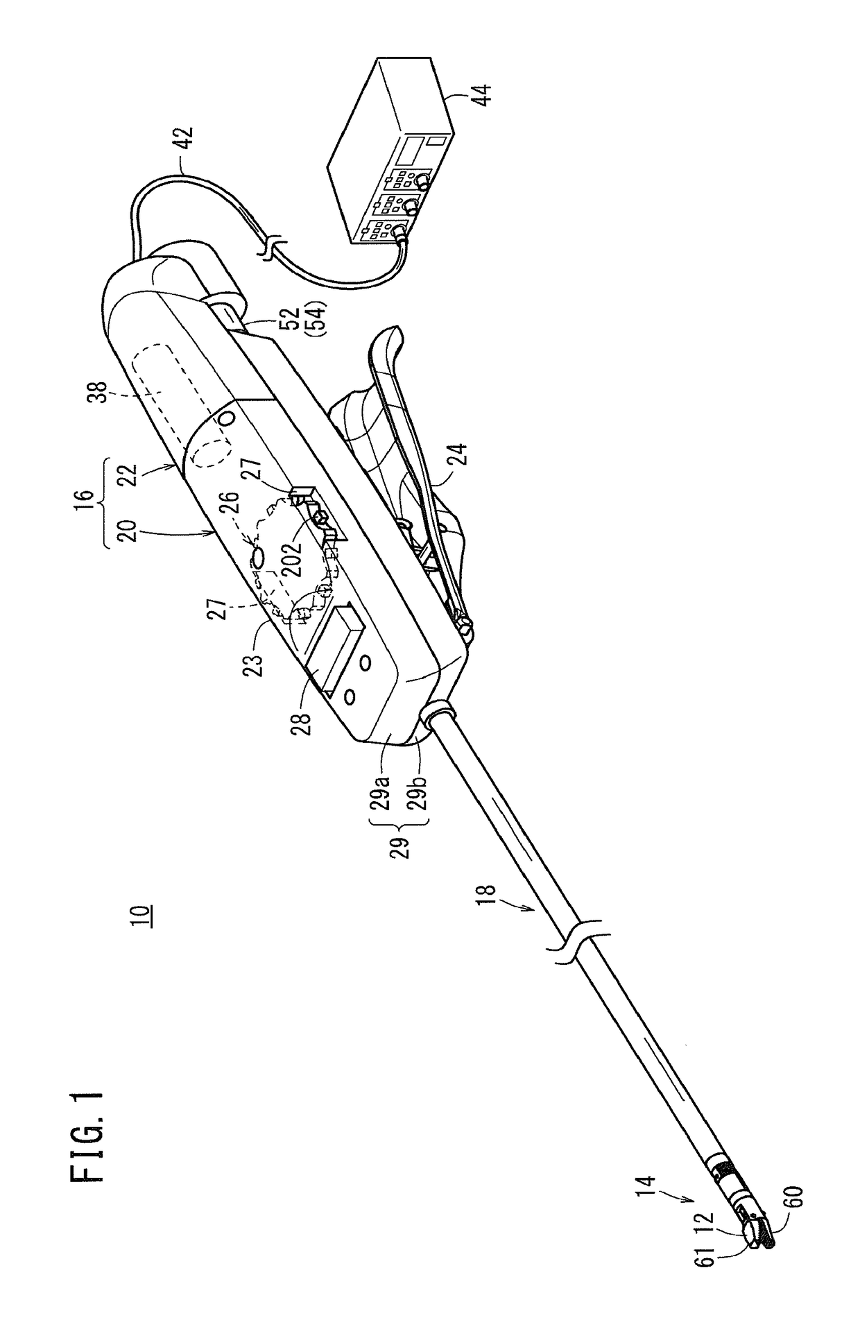
[0036]FIG. 1 is a perspective view with partial omission of a medical manipulator 10 (hereinafter referred to as a “manipulator 10”) according to an embodiment of the present invention. The manipulator 10 is a medical device that grasps a needle, a suture thread, or a part of the living body or that touches the living body using a gripper 12 (end effector) provided at the distal end thereof, and carries out a predetermined treatment. The manipulator 10 is constituted as a needle driver that is capable of grasping a medical needle (a curved needle or the like) with the gripper 12 which is disposed on the distal end thereof.

[0037]The manipulator 10 is equipped with a distal end working unit 14 (working unit) including the gripper 12, a handle 16 that drives the gripper 12, and a...


PUM


Abstract

A medical manipulator is provided with a brake release mechanism. The brake release mechanism is provided with a release button which is provided on a tilt wheel, and a lever mechanism which has at least one portion arranged on the inside of the tilt wheel and which is pressed when the release button moves inwards. By the action of the lever mechanism when the release button is operated, braking by a brake mechanism is released.

Description

FIELD OF THE INVENTION[0001]The present invention relates to a brake release mechanism and a medical manipulator provided with the same for releasing a braking action performed by a brake mechanism, which limits movement of a mechanism linked operatively with a working unit, and by which operations with respect to a rotary operating member are transmitted mechanically.BACKGROUND OF THE INVENTION[0002]In an endoscopic surgical operation (also referred to as “laparoscopic surgery”), a plurality of holes are punctured in the abdomen or the like of a patient, trocars (cylindrical instruments) are inserted through the holes, and a laparoscope (camera) and a plurality of forceps are inserted into the body cavity via each of the trocars. Grippers for gripping biological tissue, scissors, and blades of an electrosurgical knife may be mounted to the tip of the forceps as an end effector.[0003]The laparoscope and the forceps are inserted into the body cavity, and an operator then operates by ...

Claims


Application Information

Patent Timeline
Patent Type & Authority Patents(United States)
IPC IPC(8): A61B17/00F16D51/20F16D65/22F16D65/18A61B17/29A61B17/062
CPCA61B17/29F16D51/20F16D65/18F16D65/22A61B2017/2946A61B2017/00398A61B2017/2902A61B2017/2927A61B2017/2929A61B17/062
Inventor ISHIDA, SHINJISANO, HIROAKISUZUKI, TSUNEYOSHIFUKUDA, JUNICHI
Owner KARL STORZ GMBH & CO KG
Why Eureka
Try Eureka