Powder spraying system convenient to clean

A technology of powder spraying and cleaning device, which is applied in spray booths, spray devices and other directions, can solve the problems of low powder loading efficiency of automatic spray gun, powder spillage of automatic spray gun mouth, long time consuming for color change and cleaning work, etc., and achieves fast color change and cleaning work. , Reduce the amount of powder leakage, the effect of high efficiency of color changing and cleaning

Pending Publication Date: 2018-09-14
YU TUNG ZHONGSHAN ENG
View PDF15 Cites 2 Cited by
  • Summary
  • Abstract
  • Description
  • Claims
  • Application Information

AI Technical Summary

Problems solved by technology

When the sprayer cleans the side wall panels inside the powder spraying room, it is also easy to blow out the powder inside the wall panels to the outer space of the automatic spray gun slot
Therefore, the conventional powder spraying room has the following disadvantages: the automatic spray gun mouth is prone to powder overflow, the cleaning efficiency of color change is low, the cleaning of color change takes a long time, and the powder feeding efficiency of automatic spray gun is low

Method used


Image

  • Powder spraying system convenient to clean
  • Powder spraying system convenient to clean
  • Powder spraying system convenient to clean

Examples


Embodiment Construction

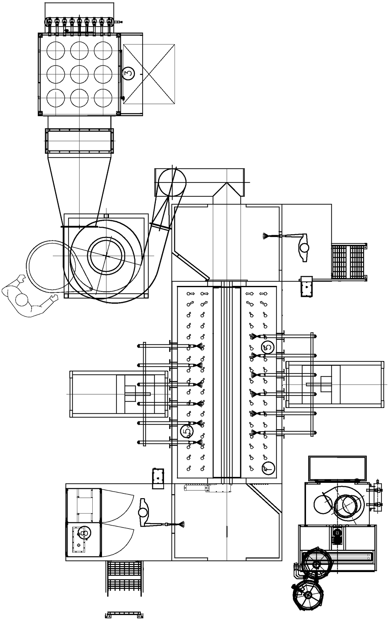
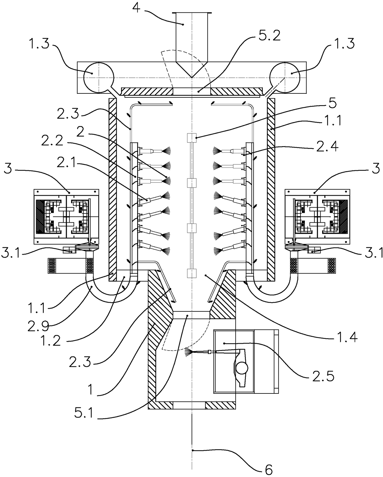
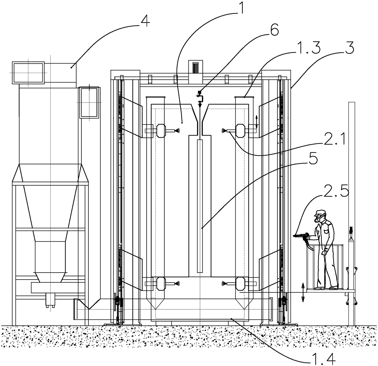
[0028] refer to figure 2 , image 3 , figure 2 and image 3 It is a structural schematic diagram of a specific embodiment of the present invention. As shown in the figure, a powder spraying system that is easy to clean includes a spray booth body 1, an automatic spray gun system 2, a vertical reciprocating device 3 and an exhaust system 4 that surround the spray area.

[0029] like figure 2 As shown, the spray booth body 1 includes a side plate assembly 1.1, a top plate assembly, a bottom plate assembly 1.4, and an exhaust duct assembly. The side plate assembly 1.1 includes a spray gun beam opening slot 1.2 parallel to the movement direction of the conveying chain 6. In this In the embodiment, the number of opening slots 1.2 of the spray gun beam on each side is only one, and the number of opening slots 1.2 of the spray gun beam is limited to be less than the number of automatic spray guns 2.1 arranged horizontally as shown in the top view projection of the automatic spr...


PUM


Abstract

The invention discloses a powder spraying system convenient to clean. The powder spraying system convenient to clean comprises a spraying chamber body sued for enclosing a spraying region, an automatic spray gun system, an air extraction system and vertical reciprocating devices; each vertical reciprocating device comprises a spray gun beam arranged on the side surface in the spraying chamber bodyand a connection arm used for connecting the spray gun beam with each vertical reciprocating device; the automatic spray gun system comprises a plurality of automatic spray guns arranged on the spraygun beams respectively; and the spraying chamber body is provided with spray gun beam opening grooves through which the connection arms penetrate respectively. A powder leakage channel is arranged ateach spray gun beam opening groove only to reduce the powder leakage quantity, and the powder is difficultly blown out to an external space of a spraying room during cleaning, so that the color change cleaning efficiency is high, a color change cleaning work is rapid, the powdering efficiency of each automatic spray gun is more efficient, and each spray gun bean is selectively equipped with a cleaning device; and each vertical reciprocating device has a function of carrying the corresponding automatic spray gun to perform vertical reciprocating motion and a function of carrying each cleaningdevice in a spraying chamber at the same time, so that the color change cleaning time is further shortened, and the spraying efficiency is improved.

Description

technical field [0001] The invention relates to an electrostatic powder spraying system, which is used in the field of automatic electrostatic powder spraying. Background technique [0002] When performing electrostatic powder automatic powder spraying operations in the powder spraying room, for the automatic spray guns arranged horizontally, the electrostatic powder spray gun is generally inserted into the powder spraying room through the automatic spray gun groove reserved on the side plate of the powder spraying room. [0003] The two sides of the powder spraying room generally reserve automatic spray gun slots with the same number of spray guns; the automatic spray gun slots on the two side plates maintain a position offset of 250mm to 500mm. The purpose of the position offset is mainly to prevent the electrostatic powder spray gun on the opposite side from The sprayed powder escapes into the space outside the spray booth. Powder spillage is most likely to occur on the ...

Claims


Application Information

Patent Timeline
Patent Type & Authority Applications(China)
IPC IPC(8): B05B13/04B05B13/02B05B15/50B05B16/60
CPCB05B13/0221B05B13/0278B05B13/041B05B15/50B05B16/60
Inventor 高敏坚柯儒群
Owner YU TUNG ZHONGSHAN ENG
Why Eureka
Try Eureka