
Synchronous powder feeding device for laser cladding machining

A technology of synchronous powder feeding and laser cladding, applied in the field of laser processing, can solve the problems of high price, powder accumulation, unsatisfactory powder feeding continuity, uniformity, etc., to improve efficiency, enhance adjustability, and realize feeding the effect of automation

Inactive Publication Date: 2014-08-20
SOUTH CHINA NORMAL UNIVERSITY
View PDF4 Cites 0 Cited by
  • Summary
  • Abstract
  • Description
  • Claims
  • Application Information

AI Technical Summary

Problems solved by technology

On the other hand, in the disclosed powder feeding devices, gas powder feeding is mostly used for powder feeding. During laser cladding processing, when the amount of powder conveyed exceeds a certain amount, if the applied gas pressure is unstable, it is easy to cause powder The accumulation makes the continuity, consistency and uniformity of powder feeding unsatisfactory
In addition, the structure of the existing cladding device is relatively complex and expensive, so it is necessary to develop a powder feeding device with a simple structure, easy to understand, easy to operate, and economical and applicable

Method used


Image

  • Synchronous powder feeding device for laser cladding machining
  • Synchronous powder feeding device for laser cladding machining
  • Synchronous powder feeding device for laser cladding machining

Examples


Embodiment Construction

[0020] Attached below Figure 1-4 An embodiment of the present invention is described.

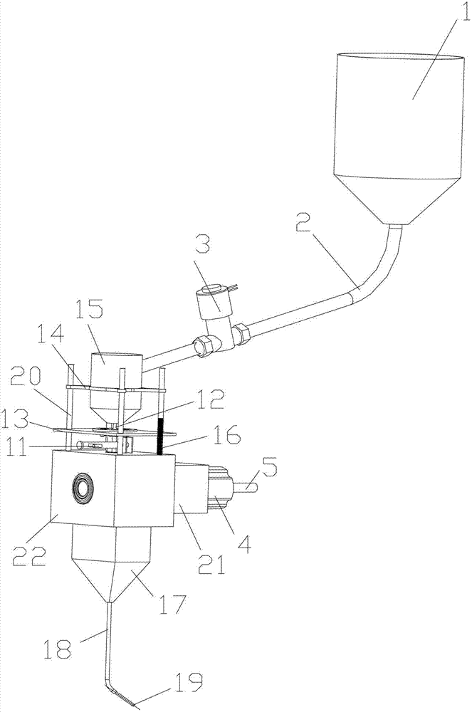
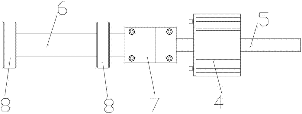
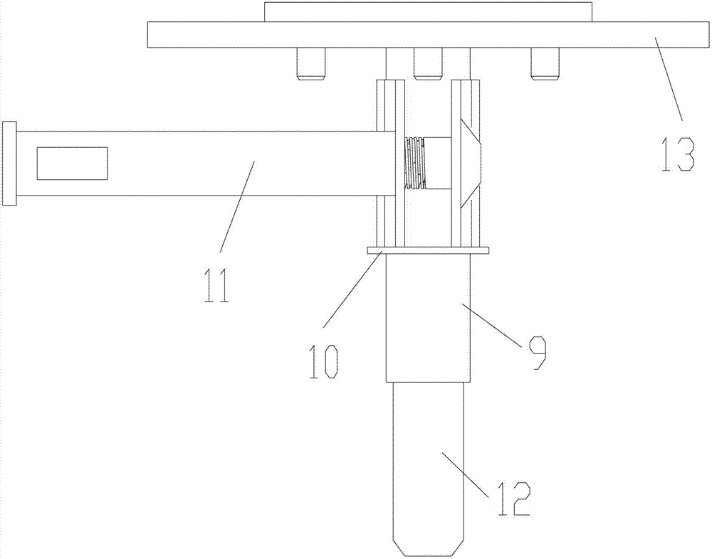
[0021] A synchronous powder feeding device for laser cladding processing, including a large powder storage bin 1, a small powder storage bin 15, a powder hopper 17, a motor 4 and a housing. The large powder storage bin 1 and the small powder storage bin 15 are connected by a plastic hose I2 And there is a solenoid valve 3 between the two, the upper end of the powder feeding shaft 12 communicates with the small powder storage bin 15, the lower end of the powder feeding shaft 12 is placed above the rotating shaft 6 and there is a gap between the two, the powder feeding shaft 12 can adjust the distance between it and the rotating shaft 6 through the adjustment device, specifically, the adjustment device includes a guide fixing frame 14, four guide shafts 24, a support plate 13, a sleeve 9 and a fastening screw 11, the The guide fixture 14 is placed on the periphery of the small powder storag...


PUM


Abstract

The invention provides a synchronous powder feeding device for laser cladding machining. The synchronous powder feeding device comprises a large-size powder storage chamber, a small-size powder storage chamber, a powder hopper, a motor and a shell; the large-size powder storage chamber and the small-size powder storage chamber are connected through a plastic hose I, and a solenoid valve is arranged between the large-size powder storage chamber and the small-size powder storage chamber; the upper end of a powder feeding shaft is communicated with the small-size powder storage chamber; the lower end of the powder feeding shaft is arranged above a rotating shaft, and an interval is reserved between the lower end of the powder feeding shaft and the rotating shaft; the powder feeding shaft can adjust a distance between the powder feeding shaft and the rotating shaft through an adjusting device; the rotating shaft is connected with an output shaft of the motor, and the rotating shaft is supported on the shell through a bearing; the upper end of the powder hopper is communicated with the shell; and the lower end of the powder hopper is connected with a nozzle through a plastic hose II. According to the synchronous powder feeding device provided by the invention, a powder falling amount can be adjusted by controlling a distance between the lower end of the powder feeding shaft and the rotating shaft. Particularly, when the powder feeding amount is large, a phenomenon of discontinuous powder feeding caused by limit on the distance between the lower end of the powder feeding shaft and the rotating shaft can be avoided. Furthermore, the time interval of two times of connection of the solenoid valve can be set, so that automatic feeding can be realized, and the production efficiency can be improved.

Description

technical field [0001] The invention relates to the field of laser processing, in particular to a synchronous powder feeding device for laser cladding processing. Background technique [0002] In the laser synchronous powder feeding cladding process, the processing quality mainly depends on the following parameters: processing speed, powder delivery rate per unit time, laser power density distribution, spot diameter and powder delivery speed; among them, powder delivery rate per unit time and powder delivery rate The speed is determined by the conveying characteristics of the powder feeder. The powder feeder is one of the core components in the laser cladding technology. It transports the set powder to the laser molten pool according to the processing technology. The performance of the powder feeder directly affects the quality of the cladding layer and the size of the processed parts, so the development of a high-performance powder feeder is particularly important for laser...

Claims


Application Information

Patent Timeline
Patent Type & Authority Patents(China)
IPC IPC(8): C23C24/10
Inventor 张健张庆茂胡玉谭小军郭亮刘颂豪
Owner SOUTH CHINA NORMAL UNIVERSITY
Learn More