Thumb-tag needle structure of hosiery knitting machine

A technology for pressing needles and sock machines, which is used in weft knitting, knitting, textiles and paper making, etc., can solve the problems of increasing the difficulty of maintenance of sock machines, uneven return force, and low positioning accuracy of rotating shafts, and achieves improved product quality. Qualification rate, flexible swing of pressing needles, and avoiding missing needles and injections

Pending Publication Date: 2018-09-14
SHAOXING HAN XIANG PRECISION MACHINERY MFG
View PDF12 Cites 0 Cited by
  • Summary
  • Abstract
  • Description
  • Claims
  • Application Information

AI Technical Summary

Problems solved by technology

[0002] In the prior art, the pressing needle structure of the hosiery machine has a large base, so it occupies a large space, making it difficult to install more parts on the upper table, which affects the efficiency of the hosiery machine
In the prior art, the pressing needle rotating shaft 31' is fixed with the base 1' by clearance fit, so that the positioning accuracy of the rotating shaft is low and the service life is short. Unevenness affects the efficiency of use. The cylinder can interrupt the connection between the knitting needle and the pressing needle. However, in the prior art, when the pressing needle 5' is pulled to one side by the knitting needle, the axis of the cylinder will be difficult to accurately align the pressing needle 5', so that The cylinder shaft 21' cannot push the press needle 5', resulting in missing needles and injections, increasing the difficulty of hosiery machine maintenance and increasing the defect rate of socks

Method used


Image

  • Thumb-tag needle structure of hosiery knitting machine
  • Thumb-tag needle structure of hosiery knitting machine
  • Thumb-tag needle structure of hosiery knitting machine

Examples


Embodiment 1

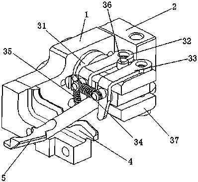
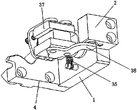
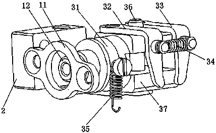
[0024] Combine below Figure 1-3 for further clarification. A needle-pressing structure of a hosiery machine of the present invention includes a base 1, a cylinder 2 is installed on one side of the base 1 (the figure shows that the cylinder 2 and the base 1 are installed by screws), and one side of the base 1 is installed on a track piece 4 , the track piece 4 is detachably installed on the side of the base 1 (the figure shows that the track piece 4 is installed on the base 1 by screws), the track piece 4 is used to adjust the track of the pressing pin 5, and the pressing pin 4 is used to It is connected in a detachable way, which can facilitate the replacement of models; the base 1 is installed with the shaft 131 through the bearing 11, and the bearing pressure plate 12 is installed on one side of the bearing 11, which can further prevent dust from entering and affecting the accuracy; the shaft, 31 is installed on one side There is a pressing pin mounting frame 38, and the p...

Embodiment 2

[0027] Others are the same as in Embodiment 1, and the cylinder 2 and the base 1 are integrally formed, which can improve the precision.


PUM


Abstract

The invention relates to a hosiery machine component, in particular to a thumb-tag needle structure of a hosiery knitting machine. The thumb-tag needle structure of the hosiery knitting machine comprises a base, wherein a cylinder is mounted on one side of the base; a track plate is mounted on the other side of the base; a first rotating shaft is mounted on the base through a bearing; a thumb-tagneedle mounting seat rack is mounted on one side of the first rotating shaft; a thumb-tag needle mounting groove is formed in the thumb-tag needle mounting seat rack; a thumb-tag needle is mounted inthe thumb-tag needle mounting groove; the thumb-tag needle mounting seat rack is connected with the thumb-tag needle through a second rotating shaft; and a pressure plate is mounted on the thumb-tag needle mounting seat rack and corresponds to the cylinder. By the thumb-tag needle structure of the hosiery knitting machine, missing and injection can be avoided, the thumb-tag needle structure returns accurately, and meanwhile, occupied space is reduced.

Description

technical field [0001] The invention relates to a hosiery machine component, in particular to a pressing needle structure of a hosiery knitting machine. Background technique [0002] In the prior art, the pressing needle structure of the sock knitting machine has a large base, so it occupies a large space, making it difficult to install more parts on the upper table, which affects the efficiency of the sock machine. In the prior art, the pressing needle rotating shaft 31' is fixed with the base 1' by clearance fit, so that the positioning accuracy of the rotating shaft is low and the service life is short. Unevenness affects the efficiency of use. The cylinder can interrupt the connection between the knitting needle and the pressing needle. However, in the prior art, when the pressing needle 5' is pulled to one side by the knitting needle, the axis of the cylinder will be difficult to accurately align the pressing needle 5', so that The cylinder shaft 21' cannot push the pr...

Claims


Application Information

Patent Timeline
Patent Type & Authority Applications(China)
IPC IPC(8): D04B15/84
CPCD04B15/84
Inventor 李鸣黄志升宋同义
Owner SHAOXING HAN XIANG PRECISION MACHINERY MFG
Why Eureka
Try Eureka