Cloth shearing device for production of safety seats

A safety seat and shearing device technology, which is applied in engineering safety devices, textile material cutting, textiles and papermaking, etc., to achieve the effects of enhancing protection, improving usability, and improving safety

Pending Publication Date: 2018-09-14
SUZHOU JISU SAFETY TECH CO LTD
View PDF0 Cites 0 Cited by
  • Summary
  • Abstract
  • Description
  • Claims
  • Application Information

AI Technical Summary

Problems solved by technology

[0002] As we all know, the fabric cutting device for safety seat production is an auxiliary device used in the production process of safety seats to cut the marked seat fabric so that it can be further cut and sewn later. , which is widely used in the field of safety seat production; the existing cloth shearing device for safety seat production includes a base, a workbench, a transmission device, a knife seat, a blade, a fixed plate and a connecting shaft, and the workbench is set on On the top of the base, the fixed plate is arranged on the rear side of the top of the left side of the workbench, the connecting shaft is arranged on the front end of the fixed plate, a placement cavity is arranged in the workbench, the transmission equipment is arranged in the placement cavity, and the tool holder is arranged on the output end of the transmission equipment. The blade is arranged on the top of the knife seat, and the top of the workbench is provided with a port, the top of the blade passes through the port and protrudes to the outside of the workbench, and the output end of the blade is located at the rear half area of ​​the top of the w

Method used


Image

  • Cloth shearing device for production of safety seats
  • Cloth shearing device for production of safety seats

Examples


Example Embodiment

[0015] The specific embodiments of the present invention will be described in further detail below in conjunction with the drawings and embodiments. The following examples are used to illustrate the present invention, but not to limit the scope of the present invention.

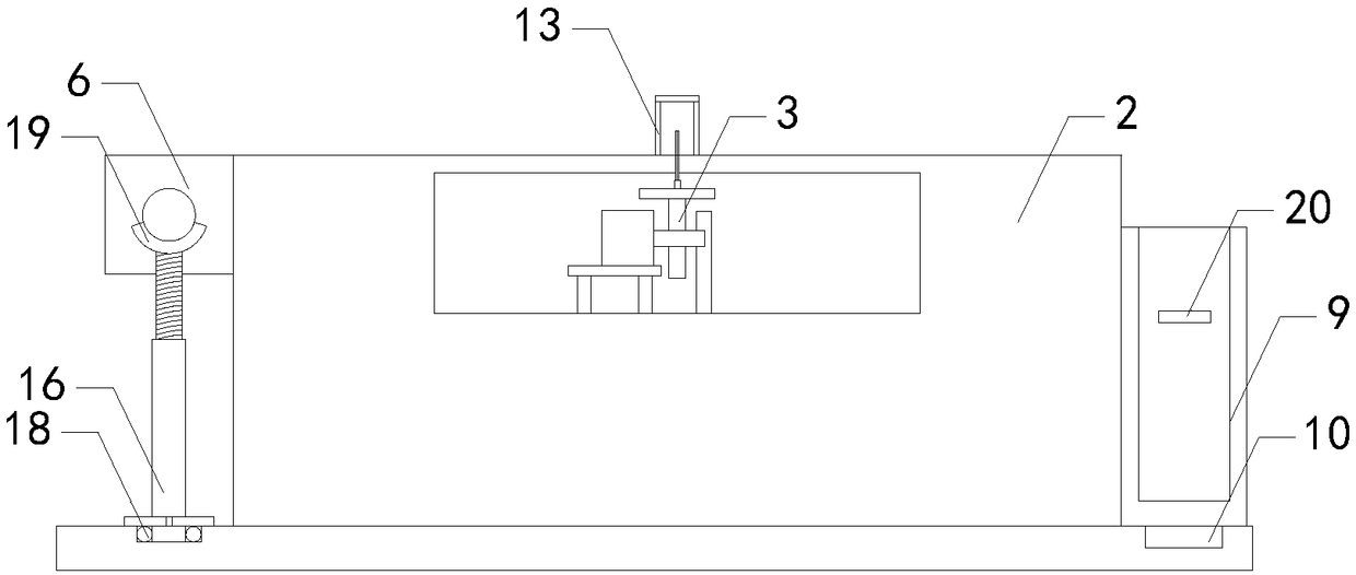
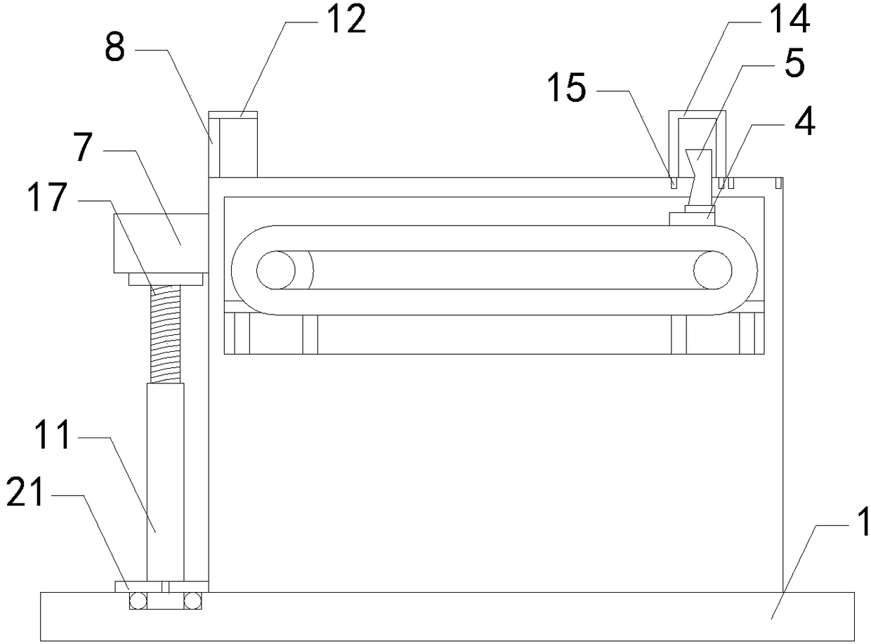
[0016] Such as figure 1 with figure 2 As shown, a cloth cutting device for the production of safety seats of the present invention includes a base 1, a working table 2, a transmission device 3, a knife holder 4, a blade 5, a fixing plate 6 and a connecting shaft 7, and the working table is arranged on the base At the top, the fixed plate is set on the rear side of the top left side of the workbench, the connecting shaft is set at the front end of the fixed plate, the workbench is provided with a placement cavity, the transmission device is set in the placement cavity, the knife holder is set on the output end of the transmission device, and the blade It is set at the top of the knife holder, the top of the wor...


PUM


Abstract

The invention relates to the technical field of auxiliary devices for production of safety seats, in particular to a cloth shearing device for production of safety seats. The effect of protecting people can be enhanced, and safety is improved; meanwhile, cloth which is shorn off can be stored conveniently, and usability is improved; and the stability of a connecting shaft after a cloth sleeve sleeves the connecting shaft is enhanced, and use reliability is improved. The cloth shearing device for production of safety seats comprises a base, a working table, transmission equipment, a knife holder, a blade, a fixing plate and a connecting shaft, and further comprises a protecting piece, a shielding piece, a placement box, a fixing block and a supporting piece, wherein the connecting shaft isarranged at the front end of the fixing plate; the knife holder is arranged on an output end of the transmission equipment; the blade is arranged at the top end of the knife holder; an output end of the blade is positioned at a rear half region of the top end of the working table; the blade is positioned on the direct rear side of the protecting piece, and is positioned in the shielding piece; thelower side surface of the placement box is in contact with the right side of the top end of the base; the supporting piece is arranged at the left front region of the top end of the base; and the topend of the supporting piece is in contact with the front side of the bottom end of the connecting shaft.

Description

technical field [0001] The invention relates to the technical field of safety seat production attachments, in particular to a cloth cutting device for safety seat production. Background technique [0002] As we all know, the fabric cutting device for safety seat production is an auxiliary device used in the production process of safety seats to cut the marked seat fabric so that it can be further cut and sewn later. , which is widely used in the field of safety seat production; the existing cloth shearing device for safety seat production includes a base, a workbench, a transmission device, a knife seat, a blade, a fixed plate and a connecting shaft, and the workbench is set on On the top of the base, the fixed plate is arranged on the rear side of the top of the left side of the workbench, the connecting shaft is arranged on the front end of the fixed plate, a placement cavity is arranged in the workbench, the transmission equipment is arranged in the placement cavity, and ...

Claims


Application Information

Patent Timeline
IPC IPC(8): D06H7/00F16P1/02
CPCD06H7/00F16P1/02
Inventor 黄晓玲
Owner SUZHOU JISU SAFETY TECH CO LTD
Why Eureka
Try Eureka